
Precise micro-type adjusting base

An adjustment seat and miniature technology, which is applied in the field of precision tool processing, can solve the problems of complicated and cumbersome positioning and adjustment of round bars, difficulty in controlling the positioning and adjustment effect, and inability to maintain the reliability of positioning and adjustment, so as to achieve good clamping force and avoid shaking , the effect of high degree of automation

Pending Publication Date: 2019-12-06
深圳市友创智能设备有限公司
View PDF0 Cites 5 Cited by
  • Summary
  • Abstract
  • Description
  • Claims
  • Application Information

AI Technical Summary

Problems solved by technology

[0003] Nowadays, when cutting micro-precision tools, in order to ensure the accuracy and quality of cutting, it is necessary to consider the levelness and concentricity error between the round bar and the grinding station, but because of the current round bar adjustment mechanism, there is no angle to which the horizontal component belongs. The relevant movable steel parts are connected to the corresponding traction to the horizontal control, and the corresponding traction connected to the vertical control rod makes relative translation with the frame up and down, left and right relative to the frame. The arc path is used to translate instead of the linear path, so it is difficult to predict the amount of displacement that can be produced by adjusting the vertical control rod or the horizontal control rod each time, which makes the positioning and adjustment of the round bar more complicated and cumbersome. And it is not easy to control the actual positioning adjustment effect, and it is relatively impossible to maintain the reliability of positioning adjustment

Method used


Image

  • Precise micro-type adjusting base
  • Precise micro-type adjusting base
  • Precise micro-type adjusting base

Examples


Embodiment Construction

[0042] The technical solution of this patent will be further described in detail below in conjunction with specific embodiments.

[0043] Embodiments of the present patent are described in detail below, examples of which are shown in the drawings, wherein the same or similar reference numerals designate the same or similar elements or elements having the same or similar functions throughout. The embodiments described below by referring to the figures are exemplary and are only used for explaining the patent, and should not be construed as limiting the patent.

[0044] In the description of this patent, it is to be understood that the terms "center", "upper", "lower", "front", "rear", "left", "right", "vertical", "horizontal", The orientation or positional relationship indicated by "top", "bottom", "inner", "outer", etc. is based on the orientation or positional relationship shown in the drawings, and is only for the convenience of describing this patent and simplifying the des...


PUM


Abstract

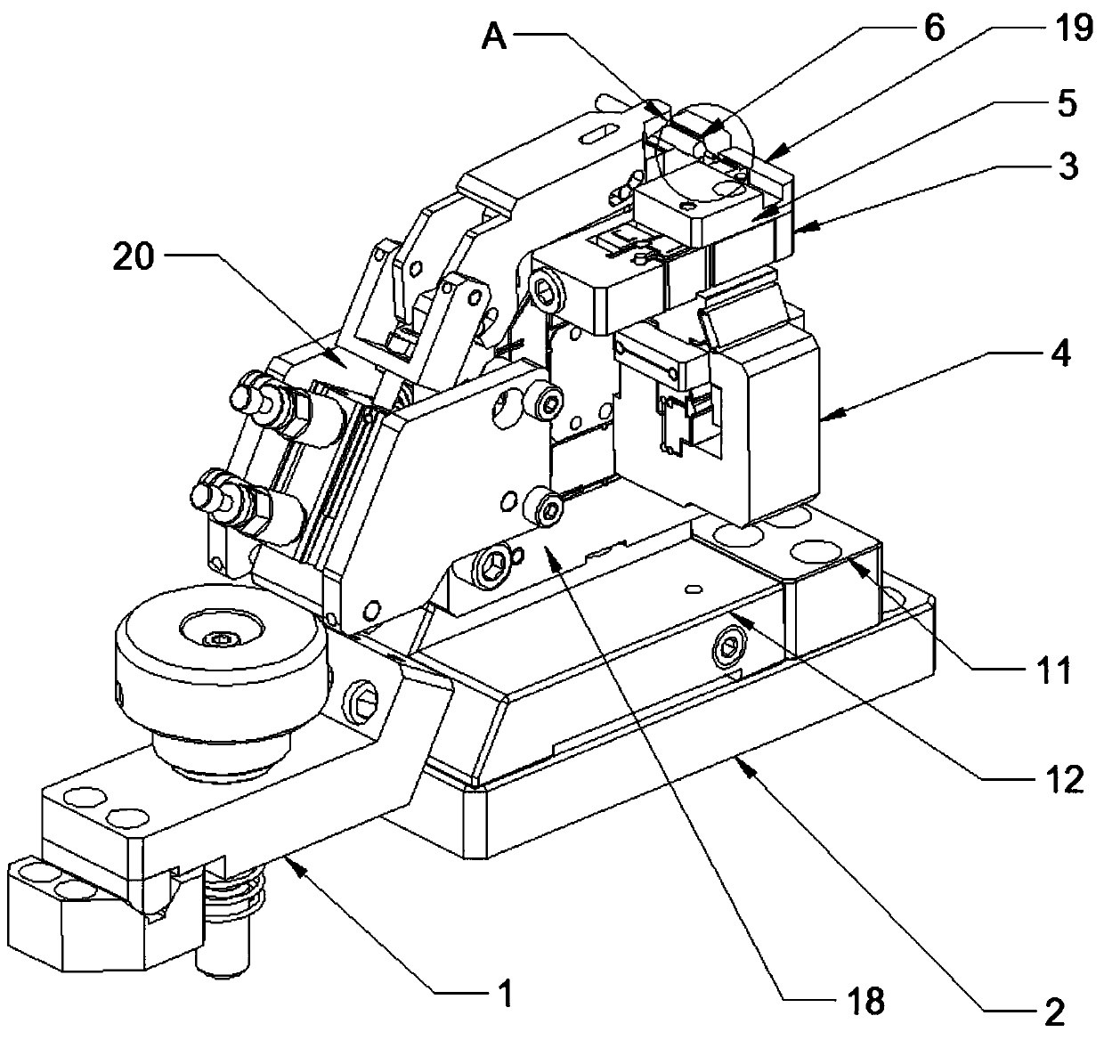
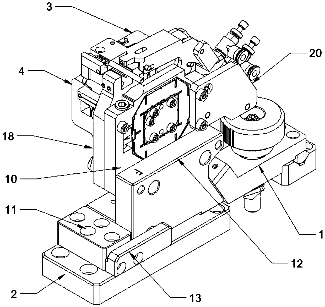
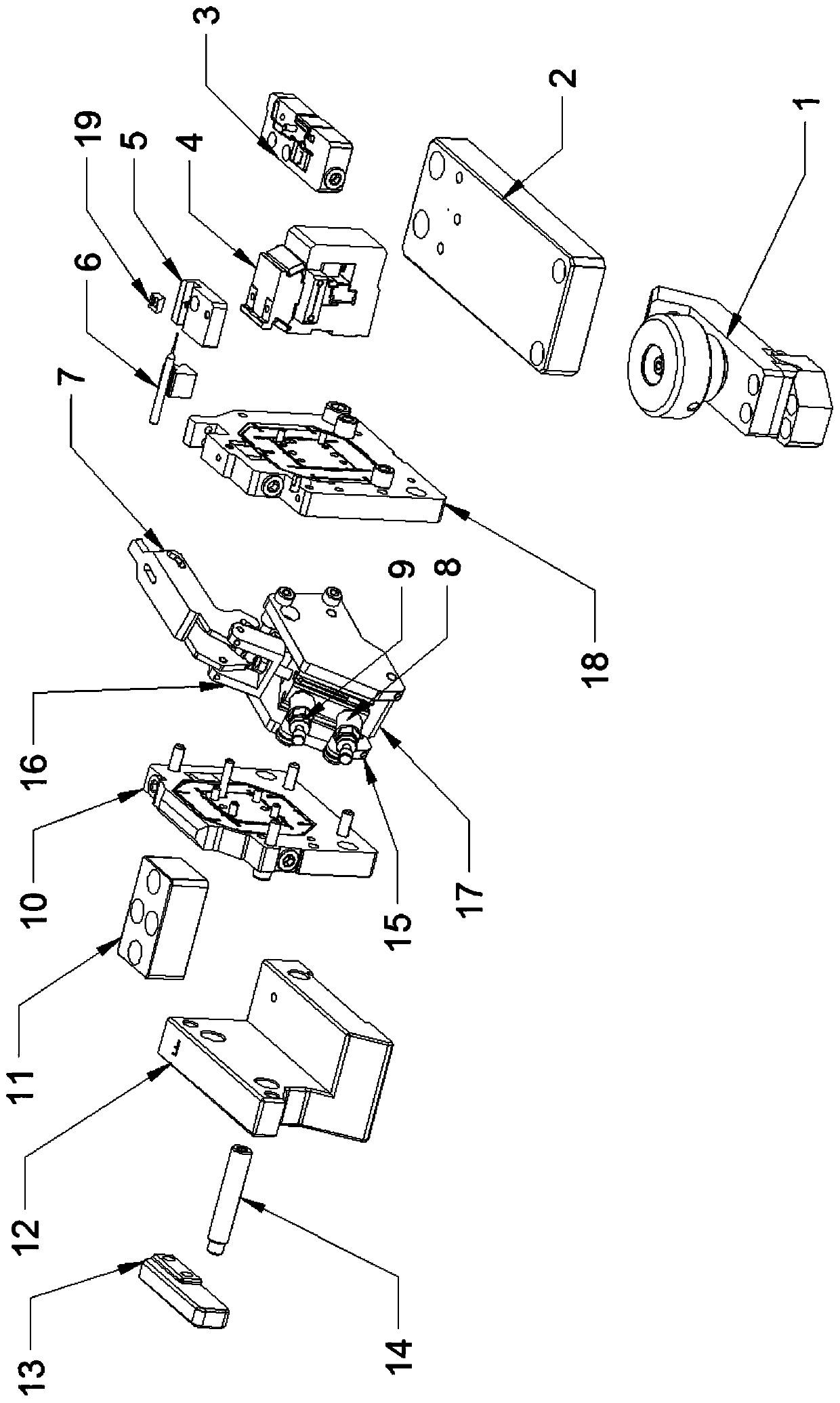
The invention provides a precise micro-type adjusting base, belongs to the technical field of machining of precision cutting tools and solves the problems about complicated location adjustment, low precision and the like in machining of a cutting tool. The precision micro-type adjusting base comprises a mounting base, a horizontal adjusting mechanism, a vertical adjusting mechanism, an X-axis adjusting plate group, a Y-axis adjusting plate group and a pressing cylinder module; the upper end of the mounting base is fixedly provided with a jig baffle block and a wedge-shaped pedestal; the end part of the wedge-shaped pedestal is provided with a hand wheel pressing mechanism; the X-axis adjusting plate group is arranged on the wedge-shaped pedestal; the Y-axis adjusting plate group is arranged at the side end of the X-axis adjusting plate group; the pressing cylinder module is arranged above the X-axis adjusting plate group and the Y-axis adjusting plate group; the vertical adjusting mechanism is arranged at the side end of the Y-axis adjusting plate group; the horizontal adjusting mechanism is arranged at the upper end of the vertical adjusting mechanism; a hardening block fixing base is arranged at the upper end of the horizontal adjusting mechanism; and a small V-shaped hardening block is fixed to the upper end of the hardening block fixing base. The precise micro-type adjusting base provided by the invention can be used for adjusting the machining position of the cutting tool by adopting multi-directional cooperation, and realizes high machining precision.

Description

technical field [0001] The invention belongs to the technical field of precision tool processing, and relates to an adjustment seat, in particular to a precision miniature adjustment seat. Background technique [0002] When cutting micro-precision tools, when assembling the required parts, the operator needs to bring the whole part close to a certain correct position of the processing station, so that the processed material meets the required processing conditions, so as to perform fine processing, and adjust the position of the bar When the frame is adjusted, it is pulled by the wire-cut chain belt, and is pulled by the chain belt connected to the vertical control rod to move up, down, left, and right relative to the frame, so that it can meet the processing requirements. [0003] Nowadays, when cutting micro-precision tools, in order to ensure the accuracy and quality of cutting, it is necessary to consider the levelness and concentricity error between the round bar and th...

Claims


Application Information

Patent Timeline
IPC IPC(8): B23Q3/06B23Q1/25
CPCB23Q3/062B23Q1/25
Inventor 阳杰
Owner 深圳市友创智能设备有限公司
Learn More