
An oxidation hanger for automatic production

An oxidizer and guide post technology, applied in anodizing, coating, electrolytic components, etc., can solve the problems of low production efficiency, high labor cost, troublesome operation, etc., and achieve the effect of high production efficiency

Active Publication Date: 2021-06-01
瑞安市一伟金属制品厂
View PDF9 Cites 1 Cited by
  • Summary
  • Abstract
  • Description
  • Claims
  • Application Information

AI Technical Summary

Problems solved by technology

[0004] The above-mentioned hanger must be manually installed on the barb by electroplating or oxidation. Not only is the operation troublesome and the labor cost is high, but once it is used for mass production of parts, the production efficiency is extremely low.

Method used


Image

  • An oxidation hanger for automatic production
  • An oxidation hanger for automatic production
  • An oxidation hanger for automatic production

Examples


Embodiment 1

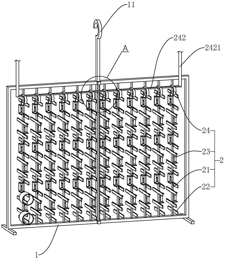
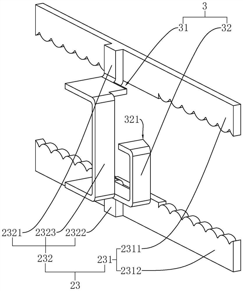
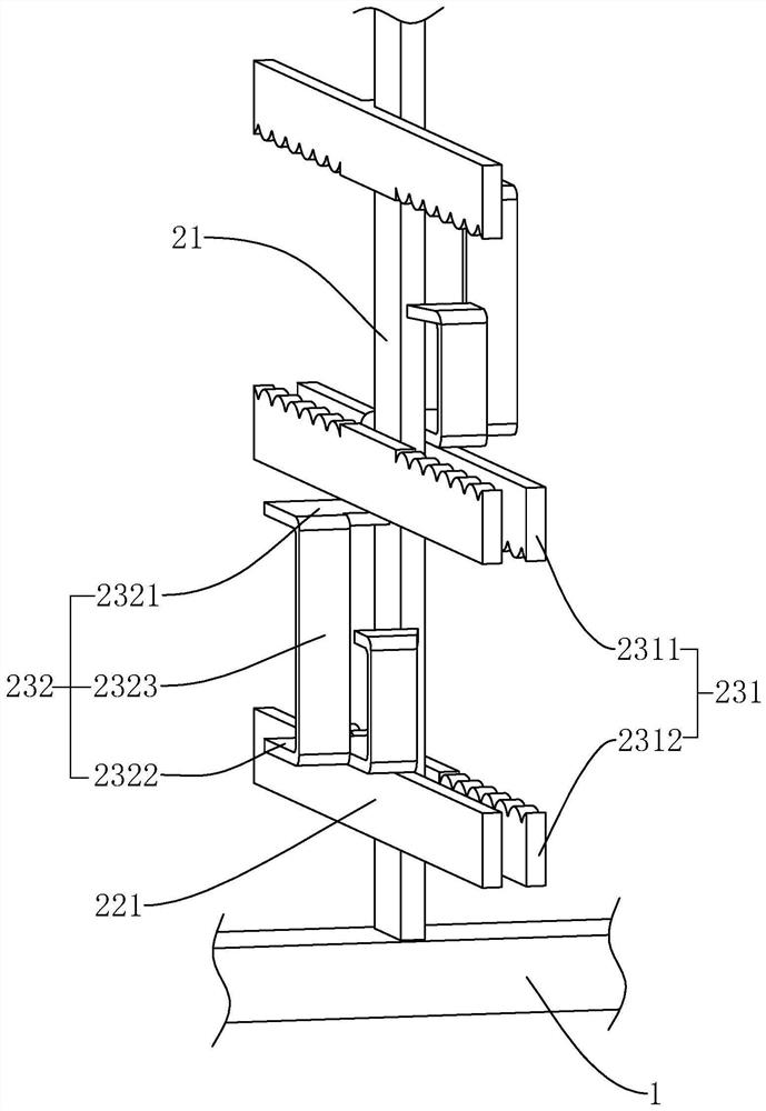
[0041] Embodiment 1, this embodiment discloses an oxidation hanger for automatic production, such as figure 1 As shown, it includes a mounting frame 1, a hook 11 arranged on the mounting frame 1, a fixing mechanism 2 for fixing workpieces to be oxidized; A positioning device 22 at the lower end of the guide post 21, a number of fixing parts 23 that are slidably connected to the guide post 21, and a limiting device 24 arranged on the fixing part 23 at the uppermost end of the guide post 21; The position of the bottom fixing part 23; the limit device 24 is used to drive the topmost fixing part 23 on the guide post 21 to move along the guide post 21; The fixing arms 231 of two adjacent fixing members 23 can realize the fixing of the workpiece to be oxidized by changing the distance between them.

[0042] like figure 1 , figure 2 As shown, the fixed arm 231 includes an upper arm 2311 and a lower arm 2312 arranged at intervals along the length direction of the guide post 21. Th...

Embodiment 2

[0054] Embodiment 2, the difference between this embodiment and Embodiment 1 is that, if Figure 8 As shown, the guide structure 3 includes two upper guide pieces 33 that are relatively arranged on the upper arm 2311 toward the middle guide post 21, and two lower guide pieces 34 that are relatively arranged on the lower arm 2312; Formed along the L-shaped or U-shaped groove and turned outwards, the lower guide piece 34 is formed by grooved along the L-shaped or U-shaped on the lower arm 2312 and turned outwards, so that between the upper guide piece 33 and the upper arm 2311, Between the lower guide piece 34 and the lower arm 2312 are respectively formed guide passages 31 corresponding to the cross-sectional shape of the guide post 21 . The upper guide piece 33 and the lower guide piece 34 are respectively formed by bending and slotting on the upper arm 2311 and the lower arm 2312 , which has a simple structure, saves materials, and is easy to process. The upper guide piece 3...


PUM


Abstract

The present invention relates to the technical field of oxidation hangers, and aims to provide an oxidation hanger for automatic production, including a mounting frame, a guide post arranged on the mounting frame, and several fixing parts slidingly connected to the guide posts; the fixing parts include Fixing arms extending toward both sides of the guide post; the position of the fixing piece at one end is limited by the positioning device, and the fixing piece at the other end is pushed toward the positioning device by the limiting device, so that all the fixing pieces are close to each other, and then the cap At the same time, it is sleeved on two adjacent fixed arms to realize the series connection of all the fixed parts, and then use the limit device to drive the fixed parts to move away from each other, so that the two fixed arms with increasing spacing are used to support the pipe cap. On the inner walls of the upper and lower ends, the effect of extrusion and fixing is realized; the distance between the fixing arms can be adjusted, which is convenient for the sleeve placement of pipe caps, and is suitable for batch operation of automated equipment, with higher production efficiency.

Description

technical field [0001] The invention relates to the technical field of oxidation racks, in particular to an oxidation rack for automatic production. Background technique [0002] Electroplating is the process of plating a layer of metal or alloy on the surface of some metals by using the principle of electrolysis, so as to prevent corrosion, improve wear resistance, conductivity and enhance the appearance. When some products are electroplated, it is necessary to hang the product on the rack, and then put the product into the electroplating solution tank for electroplating. The rack mainly plays the role of conducting, supporting and fixing parts. The same hanger is also applicable to the oxidation reaction on the surface of metal products. Oxidation is to form an oxide film on the surface of parts through nitrite. [0003] At present, the Chinese patent document with the application publication number CN109706509A in the prior art discloses a portable electroplating hanger ...

Claims


Application Information

Patent Timeline
Patent Type & Authority Patents(China)
IPC IPC(8): C25D17/08C25D11/02
CPCC25D11/005C25D11/02
Inventor 钱明伟
Owner 瑞安市一伟金属制品厂
Learn More