
Mode demultiplexer of degenerate mode group based on spatial three-dimensional waveguide

A demultiplexer and mode group technology, applied in the field of demultiplexers, can solve the problems of difficult device implementation, long coupling area, and strict directional coupling conditions, so as to avoid digital signal processing, improve coupling efficiency, and reduce Realize the effect of cost

Pending Publication Date: 2019-12-06
PEKING UNIV
View PDF10 Cites 5 Cited by
  • Summary
  • Abstract
  • Description
  • Claims
  • Application Information

AI Technical Summary

Problems solved by technology

However, due to the strict directional coupling conditions between high-order modes and the need to take into account the coupling of the two modes at the same time, it is too difficult to realize the device, the coupling region is long, and the device efficiency is generally low.

Method used


Image

  • Mode demultiplexer of degenerate mode group based on spatial three-dimensional waveguide
  • Mode demultiplexer of degenerate mode group based on spatial three-dimensional waveguide
  • Mode demultiplexer of degenerate mode group based on spatial three-dimensional waveguide

Examples


Embodiment Construction

[0036] In order to make the purpose, technical solution and advantages of the present invention clearer, the following degenerate mode group LP 21 The manufacturing method of the demultiplexer is taken as an example and the present invention is described in detail in conjunction with the accompanying drawings. It should be understood that the specific examples described here are only used to explain the present invention, not to limit the present invention.

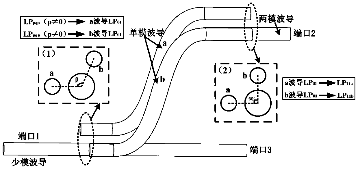
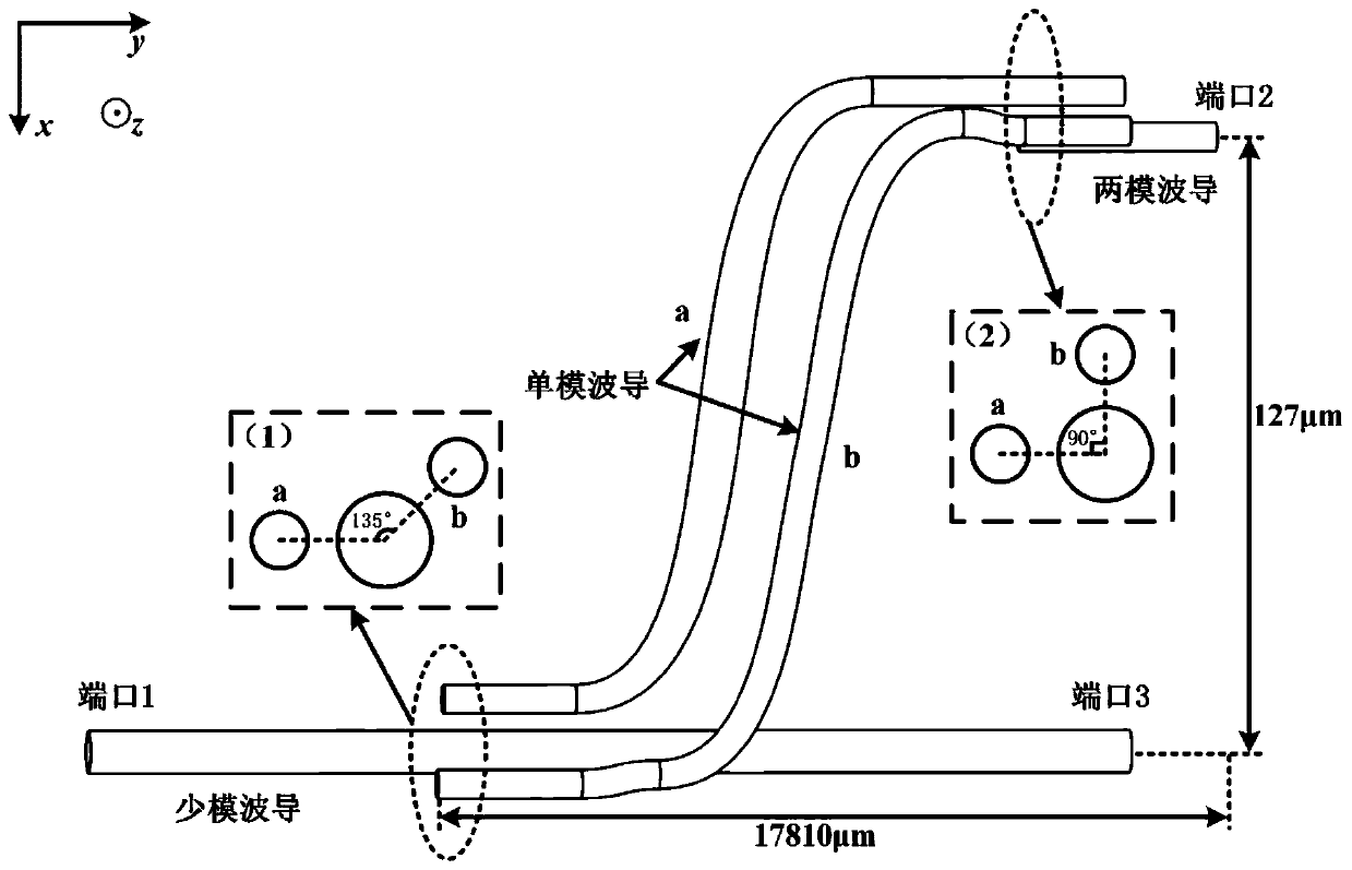
[0037] image 3 is the degenerate pattern group LP 21 Example of demultiplexing, in this case a few-mode waveguide supporting four mode LPs 01 , LP 11 , LP 21 and LP 02 . The entire device design is in borosilicate glass with a background refractive index of 1.4877, the refractive index of the few-mode waveguide is 1.499, and the diameter is 12.18 μm; the refractive index of single-mode waveguides a and b are both 1.4928, and the diameter is 8.2 μm ; The refractive index of the two-mode waveguide is 1.499 and the d...


PUM


Abstract

The invention discloses a mode demultiplexer of a degenerate mode group based on a spatial three-dimensional waveguide. The mode demultiplexer is characterized in that the mode demultiplexer comprisesa few-mode waveguide and two single-mode waveguides. One end of the first single-mode waveguide is coupled to the few-mode waveguide, and at the coupling position, the axial direction of the first single-mode waveguide is the same as that of the few-mode waveguide; the other end of the first single-mode waveguide is connected with one end of a single-mode straight waveguide through an S-shaped bend waveguide; one end of the second single-mode waveguide is coupled to the few-mode waveguide, and the other end of the second single-mode waveguide is connected with one end of a single-mode straight waveguide through an S-shaped bend waveguide; the other ends of the two single-mode straight waveguides are coupled to one end of a two-mode waveguide, and an included angle formed by connecting lines of circle centers is 90 degrees; a port 1 of the few-mode waveguide receives a few-mode signal in a mixed mode; and the other end of the two-mode waveguide couples the modes LPpqa and LPpqb input into the few-mode waveguide to LP11a and LP11b of the two-mode waveguide correspondingly and then, outputs the modes LP11a and LP11b, wherein p is not equal to 0.

Description

technical field [0001] The invention relates to a demultiplexing structure of a degenerate mode group, in particular to a demultiplexer for separately demultiplexing and recombining a degenerate mode group based on a spatial three-dimensional waveguide, which can be applied to new technologies such as optical fiber communication and optical information processing. Generation information technology field. Background technique [0002] In recent years, in order to meet the capacity requirements of optical fiber communication systems, mode division multiplexing technology has become one of the research hotspots in the field of optical fiber communication, and the mode multiplexer / demultiplexer as one of its key technologies has received extensive attention. Since the crosstalk between the patterns within each pattern group is large, the crosstalk between the pattern groups is very low. Therefore, in the long-distance mode division multiplexing system, it is necessary to use mu...

Claims


Application Information

Patent Timeline
IPC IPC(8): G02B6/293
CPCG02B6/2938
Inventor 李巨浩杨宇陈章渊何永琪
Owner PEKING UNIV
Learn More