
Inverted-H-shaped beam assembly equipment and inverted-H-shaped beam manufacturing method

A manufacturing method and I-beam technology, applied in the direction of metal processing equipment, manufacturing tools, welding equipment, etc., can solve the problems of affecting production efficiency, relying heavily on personnel quality, and consuming man-hours, so as to reduce the degree of dependence on people and control the overall Assembling accuracy and the effect of reducing labor intensity

Pending Publication Date: 2019-12-10
YANGZHOU CIMC TONGHUA SPECIAL VEHICLES +1
View PDF0 Cites 3 Cited by
  • Summary
  • Abstract
  • Description
  • Claims
  • Application Information

AI Technical Summary

Problems solved by technology

However, for variable-section I-beams, the lower wing plate needs to be pre-bent and formed before assembly. It is difficult to realize automatic loading and assembly on the assembly table. It needs to rely on manual handling of parts and assembly positioning, which is highly dependent on the quality of personnel and product quality. Large artificial influence, poor product consistency, and time-consuming, affecting production efficiency

Method used


Image

  • Inverted-H-shaped beam assembly equipment and inverted-H-shaped beam manufacturing method
  • Inverted-H-shaped beam assembly equipment and inverted-H-shaped beam manufacturing method
  • Inverted-H-shaped beam assembly equipment and inverted-H-shaped beam manufacturing method

Examples


Embodiment Construction

[0059] Typical embodiments that embody the features and advantages of the present invention will be described in detail in the following description. It should be understood that the present invention is capable of various changes in different embodiments without departing from the scope of the present invention, and that the description and illustrations therein are illustrative in nature and not limiting. this invention.

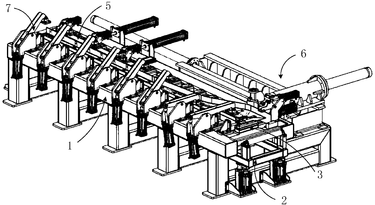
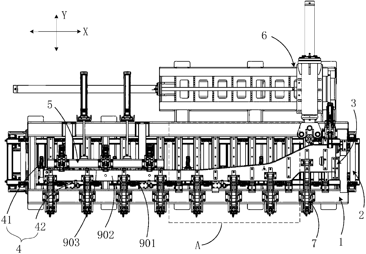
[0060] The invention relates to an I-beam assembling device (hereinafter referred to as the assembling device), which is used for assembling an upper flange, a web, and a lower flange in a steel plate state into a variable-section I-beam. The variable-section I-beam has a fixed section and a variable section, and is especially suitable as a longitudinal beam for the frame of semi-trailers such as straight-back frame vehicles, small gooseneck frame vehicles, straight-back flat rail bins, and gooseneck flat rail bins. .

[0061] refer to figure 1 and fi...


PUM


Abstract

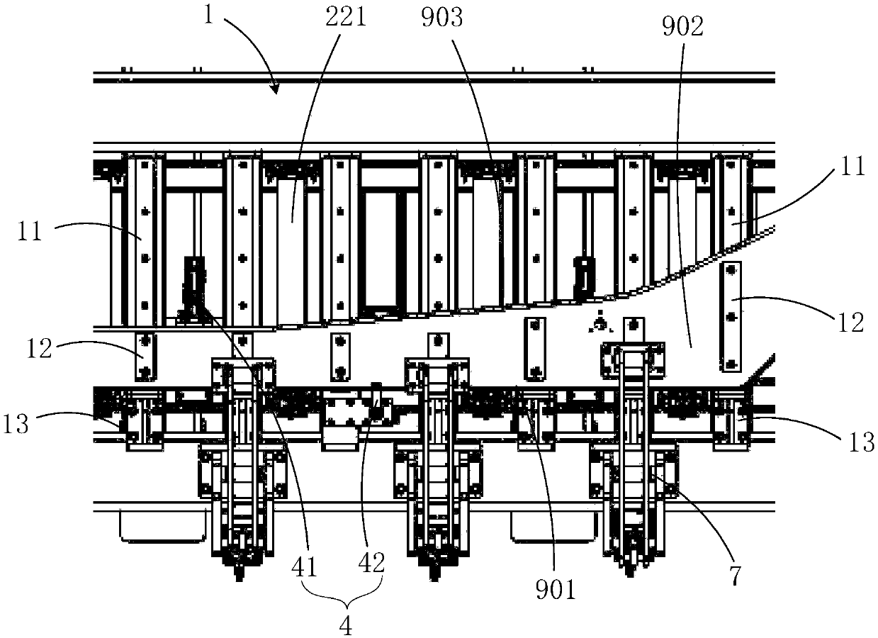
The invention provides inverted-H-shaped beam assembly equipment and an inverted-H-shaped beam manufacturing method. The inverted-H-shaped beam assembly equipment comprises an assembly table, a transfer mechanism, a positioning mechanism, an upper wing plate pressing mechanism, a linear section pressing mechanism and a variable-section section pressing and forming mechanism, wherein a web supporting surface, an upper wing plate positioning slot and a lower wing plate placing slot are formed in the assembly table for separately, correspondingly and completely support a web, an upper wing plateand a lower wing plate in a length direction of an inverted-H-shaped beam; the transfer mechanism is provided with a transfer roller way which can ascend and descend relative to the assembly table; the positioning mechanism is used for positioning the web, the upper wing plate and the lower wing plate in the length direction of the assembly table; the upper web pressing mechanism is used for positioning and fixing the upper wing plate into an upper wing plate supporting slot; the linear section pressing mechanism is used for pushing the lower wing plate to move towards the upper wing plate toassemble to form a fixed-section section of the inverted-H-shaped beam; and the variable-section section pressing and forming mechanism is used for pushing the lower wing plate to move towards the upper wing plate on multiple positions in the length direction of the lower wing plate, pressing and bending the lower wing plate to be consistent with the edge of the web in shape to assemble to form the variable-section section of the inverted-H-shaped beam.

Description

technical field [0001] The invention relates to the field of I-beam manufacturing, in particular to an I-beam assembling device and a method for manufacturing the I-beam. Background technique [0002] The semi-trailer longitudinal beam is a very important load-bearing part in the entire semi-trailer structure. It needs to bear the weight of the body itself and the loaded goods. Its welding quality directly determines the quality of the entire semi-trailer. Due to the structural requirements for use with the tractor, the longitudinal beam of the semi-trailer is generally a variable-section I-beam structure, that is, the shape of the web is not a regular rectangle, but a variable-section section with a variable width. Correspondingly, in order to attach If the web is closed, the lower flange will have a bent section. [0003] In the prior art, there are roughly the following methods for forming such variable-section I-beams: [0004] 1. Adopt automatic welding and forming eq...

Claims


Application Information

Patent Timeline
Patent Type & Authority Applications(China)
IPC IPC(8): B23P19/00B23K37/00B23K37/04
CPCB23K37/00B23K37/04B23K37/0443B23P19/00
Inventor 李东浩张世炜李晓甫张新龙
Owner YANGZHOU CIMC TONGHUA SPECIAL VEHICLES
Learn More