Antenna cover plate profiling prefabricated member puncture method and antenna cover plate forming method

A prefabricated part and antenna cover technology, which is applied in the field of antenna cover molding and antenna cover profiling prefab puncture, can solve the problems of low overall strength and weak force on the radome cover, so as to avoid unbalanced force. , high overall strength and performance, the effect of reducing the amount of

Active Publication Date: 2019-12-10
CHANGSHA JINGYOU NEW MATERIAL TECH CO LTD
View PDF6 Cites 4 Cited by
  • Summary
  • Abstract
  • Description
  • Claims
  • Application Information

AI Technical Summary

Problems solved by technology

[0004] The invention provides a method for puncturing a profiling prefabricated part of an antenna cover plate and a method for forming an antenna cover plate, which are used to overcome defects such as weak force-bearing areas and low overall strength of the radome cover plate in the prior art, and improve the force bearing capacity of the overall structure Balance and overall strength, reducing the amount of fiber raw material and processing costs

Method used


Image

  • Antenna cover plate profiling prefabricated member puncture method and antenna cover plate forming method
  • Antenna cover plate profiling prefabricated member puncture method and antenna cover plate forming method
  • Antenna cover plate profiling prefabricated member puncture method and antenna cover plate forming method

Examples


Embodiment 1

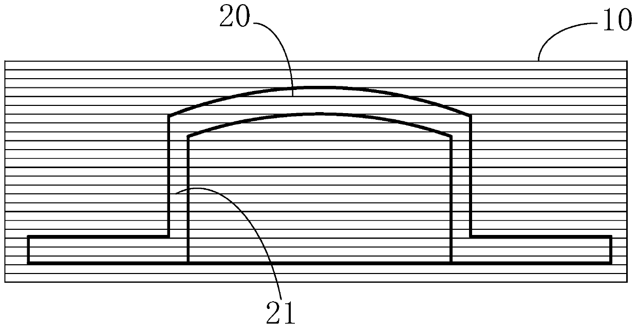
[0032] as attached figure 2 Shown, a kind of puncture method of profiling prefabricated part of antenna cover plate, comprises the following steps:

[0033] S1, continuously laying a layer of fiber cloth on the outer surface of the mold;

[0034] The fiber cloth is made of woven cloth layer, which is formed by two-way fiber weaving. The fiber cloth is covered on the mold, and the center position is aligned with the center of the raised top surface of the mold to reduce the waste of raw materials.

[0035] S2, adjusting the fiber gap of the fiber cloth on the raised part of the mold so that the fiber cloth coincides with the outer surface of the mold and forms a fiber cover;

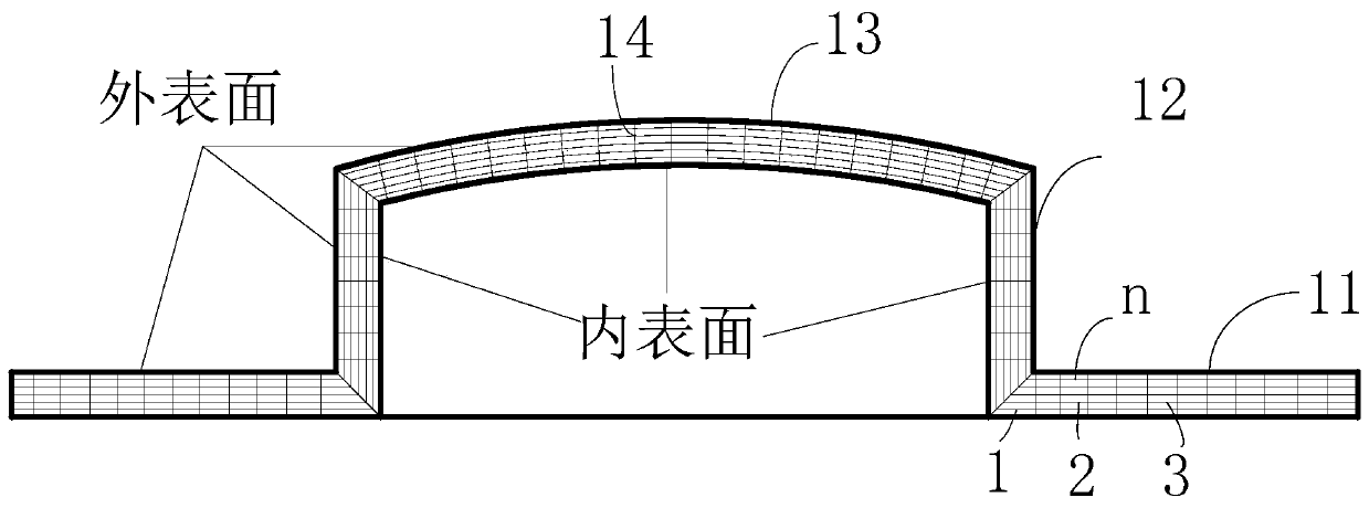
[0036] This process can be adjusted manually or through the mold. Yes, the fiber cloth is deformed by the gap between the vertical and horizontal fibers. After deformation, a three-dimensional fiber cover is formed. The fiber cover here covers the outer surface of the mold as a whole. And it is the sam...

Embodiment 2

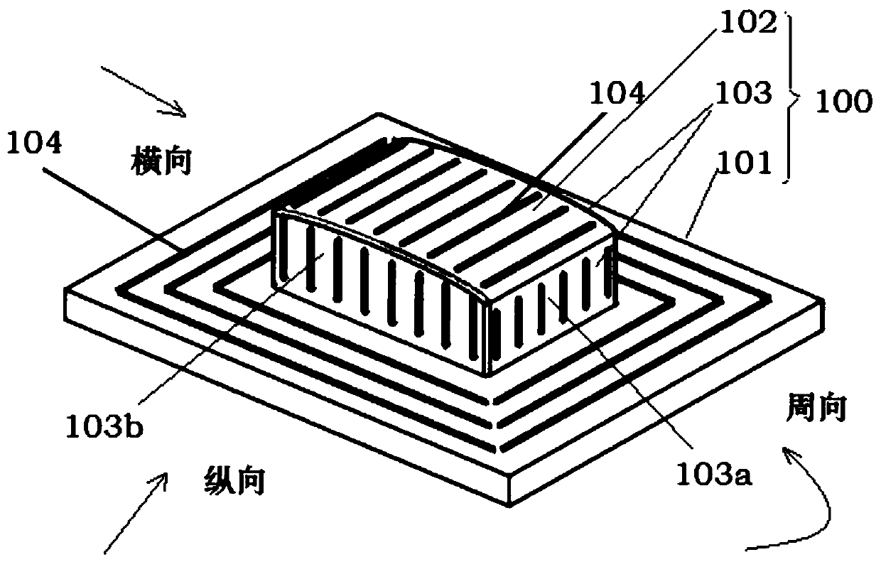
[0074] Based on the first embodiment above, the embodiment of the present invention also provides a method for forming an antenna cover, including the following steps:

[0075] The preform is prepared by the puncture method of the profiling preform of the antenna cover plate in any of the above embodiments;

[0076] Use two rigid molds to clamp both sides of the prefabricated part in the thickness direction, and adjust the gap between the two rigid molds according to the control margin to control the thickness of the prefabricated part within the preset range; The gap between the rigid molds, until the preform reaches the pre-controlled thickness, the common way to fix the inner rigid mold, apply pressure to the outer rigid mold, when the pre-controlled thickness range is reached, fix the inner and outer rigid molds (such as bolt connection and other methods) , to maintain a gap between the two to control the preform thickness;

[0077] Put the two rigid molds and the preform...


PUM

PropertyMeasurementUnit
thicknessaaaaaaaaaa

Abstract

The invention discloses an antenna cover plate profiling prefabricated member puncture method and an antenna cover plate forming method. The puncture method comprises the following steps that a layerof fiber cloth is continuously laid on the outer surface of a mold; the fiber gap of the fibre cloth on the protruding part of the mold is adjusted to enable the fiber cloth to be matched with the outer surface of the mold, and a fiber cover is formed; laying and adjusting of multiple layers of fiber cloth are repeated, when the laid fiber cloth layers reach the preset number, laying of one stacking unit is finished; laying of multiple stacking units is repeated, in the laying process of the stacking units, at least two adjacent units are sewn until the preset thickness is achieved; and through sewing is carried out on the mold along a sewing groove, demolding is carried out, and in the whole thickness direction, through sewing is achieved. The problem that in the prior art, local stress is weak, and the raw material is wasted is solved, strength of an antenna cover plate profiling prefabricated member is improved, and the cost is reduced.

Description

technical field [0001] The invention relates to the technical field of aerospace prefabricated parts, in particular to a method for puncturing an antenna cover profiling prefabricated part and a method for forming an antenna cover. Background technique [0002] Due to factors such as the use environment of the antenna in the aerospace field, in order to protect the antenna, the antenna is usually placed in the space surrounded by the radome and the antenna cover. The radome and the antenna cover need to be made of wave-transparent materials and have a certain strength. Radome and cover are usually obtained by reprocessing prefabricated parts. [0003] see figure 1 , the existing antenna cover plate is obtained by machining the plate preform 10 formed by stacking or weaving multiple layers of fiber cloth. The side of the antenna cover plate 20 obtained by this method is obtained by longitudinally shearing the interlayer fibers. The height direction of the side surface is fo...

Claims


Application Information

Patent Timeline
Patent Type & Authority Applications(China)
IPC IPC(8): B29C70/34B29C70/54
CPCB29C70/345B29C70/54
Inventor 不公告发明人
Owner CHANGSHA JINGYOU NEW MATERIAL TECH CO LTD
Why Eureka
Try Eureka