An improved frame type hoisting device
A lifting device and frame-type technology, which is applied in the field of opto-mechanical-electrical integration equipment, can solve the problems of easy wear, bad, complicated and cumbersome adjustment of wire rope length, and achieve the effect of avoiding cumbersome and complicated, increasing stability and safety
- Summary
- Abstract
- Description
- Claims
- Application Information
AI Technical Summary
Problems solved by technology
Method used
Image
Examples
Embodiment 1
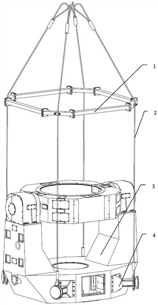
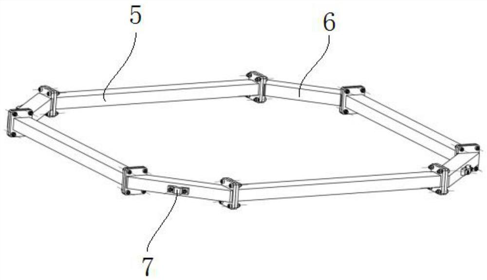
[0110] In order to form an assembly with the steel wire rope assembly seat 6, it not only ensures the structural stability after assembly, but also ensures the formation of a rotational connection with the steel wire rope assembly seat 6 after installation, which is convenient for the adjustment of the corresponding steel wire rope. There are certain structural requirements, as described below;
[0111] The upper steel wire rope assembly 2 includes four upper steel wire ropes 201, the upper ends of the upper steel wire ropes 201 are bound and fixed with a first ring sleeve 202 through an aluminum alloy pressure sleeve 7, and the lower ends of the upper steel wire ropes 201 are bound with a second ring sleeve 203 through an aluminum alloy pressure sleeve 7;
[0112] The upper wire rope 201 is connected to the hook of the lifting device through the first ring sleeve 202;
[0113] The second ring sleeve 203 of the upper wire rope 201 is sheathed in the U-shaped groove 10 of the f...
Embodiment 2
[0118] In order to form a connection with the extension arm assembly 4 added in this embodiment, the lower wire rope 301 and the extension arm assembly 4 have certain structural requirements, specifically as follows:
[0119] The lower steel wire rope assembly 3 includes four lower steel wire ropes 301, and the lower end of the lower steel wire ropes 301 is bound and fixed with a fourth ring sleeve 303 through the aluminum alloy compression sleeve 7;
[0120] The fourth ring sleeve 303 of the lower wire rope 301 is sheathed in the U-shaped groove 10 of the third sleeve 406 and forms a rotational connection with the third sleeve 406 .
[0121] Similar to the structural principle in Embodiment 1, a third shaft 405 and a third bushing 406 are installed on the upper part of the extension arm assembly 4, wherein the middle part of the third bushing 406 is formed with U-shaped grooves 10 distributed along its radial direction. The third shaft sleeve 406 cooperates, and the lower end...
PUM
 Abstract
Description
Claims
Application Information
 - R&D
- Intellectual Property
- Life Sciences
- Materials
- Tech Scout
- Unparalleled Data Quality
- Higher Quality Content
- 60% Fewer Hallucinations
Browse by: Latest US Patents, China's latest patents, Technical Efficacy Thesaurus, Application Domain, Technology Topic, Popular Technical Reports.
© 2025 PatSnap. All rights reserved.Legal|Privacy policy|Modern Slavery Act Transparency Statement|Sitemap|About US| Contact US: help@patsnap.com


