Automatic liquid drainage system

A technology of automatic drainage and exhaust pipe, which is applied in the fields of pressure vessel manufacturing and automatic drainage system, can solve the problem that the valve body does not have action characteristics, and achieve the effect of avoiding danger.

Inactive Publication Date: 2019-12-10
李凤英
View PDF0 Cites 0 Cited by
  • Summary
  • Abstract
  • Description
  • Claims
  • Application Information

AI Technical Summary

Problems solved by technology

[0005] The invention provides an automatic liquid discharge system for automatic control of liquid discharge to solve the technical problem that the valve body does not have action characteristics when there is high-pressure gas in the tank in the prior art

Method used


Image

  • Automatic liquid drainage system
  • Automatic liquid drainage system
  • Automatic liquid drainage system

Examples


Embodiment Construction

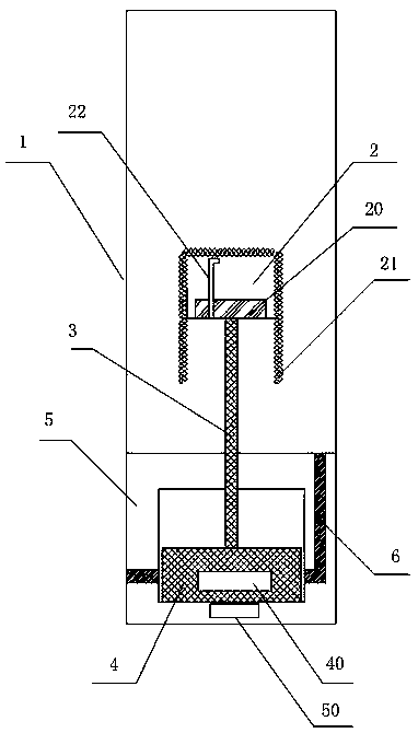
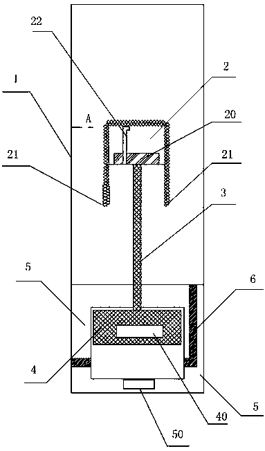
[0019] Such as figure 1 , figure 2 The automatic draining system of this embodiment includes: a tank body 1 and a ball float valve; The valve body 5 at the bottom; the tank body 1 is generally a closed cavity for storing various liquids.

[0020] The valve body 5 is provided with a drain channel 6 for connecting the tank body 1 with the outside world; the drain channel connects the tank body with the outside world, and when the liquid level is too high, the liquid is drained through the drain channel.

[0021] The valve body 5 is also sleeved with a slidable valve core 4, and the valve core 4 slides up and down to open or close the drain channel 6; as shown in the figure, the drain channel opens when the valve core slides up; When the spool slides, the discharge passage is cut off by the spool and the discharge is closed.

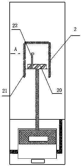
[0022] One end of the connecting rod 3 is connected with the floating ball 2 , and the other end is connected with the valve core 4 .

[0023] The bot...


PUM


Abstract

The invention provides an automatic liquid drainage system and relates to the field of pressure pipeline equipment. The automatic liquid drainage system comprises a tank and a floating ball valve. Thefloating ball valve comprises a connecting rod, a floating ball and a valve body. A liquid drainage channel is formed in the valve body. A valve element capable of sliding is arranged in the valve body in a sleeved manner. The valve element slides up and down to open and close the liquid drainage channel. The two ends of the connecting rod are connected with the floating ball and the valve element. An ultrasonic transducer is arranged on the bottom of the floating ball. An exhausting pipe is further arranged in the floating ball. An inlet of the exhausting pipe is formed in the bottom of theultrasonic transducer. An outlet of the exhausting pipe is formed in the floating ball and located in the upper portion of the floating ball. An expanding floating ball is adopted as the floating ball. According to the system, the liquid level is controlled by means of the floating ball, when much dissolving gas exists in the tank, the floating ball becomes large, and can keep the liquid drainagestate all the time, and the risk is avoided.

Description

technical field [0001] The invention relates to pressure vessel manufacturing technology, in particular to an automatic liquid drainage system, which belongs to the technical field of pipeline equipment manufacturing. Background technique [0002] In the application process of the liquid storage system, the liquid level float is a common control component. The principle of float control is to use the float of the float level switch to rise or fall with the liquid level, so that the valve body or switch parts can make corresponding actions to realize the automatic control of the liquid level. [0003] The automatic control valve in the prior art, due to the characteristics of simple buoyancy control, does not have the ability to respond when high-pressure gas appears in the tank, and it is easy to cause safety accidents due to other effects of high pressure in the tank. [0004] The existing liquid storage system has the following technical problem, that is, when there is hi...

Claims


Application Information

Patent Timeline
Patent Type & Authority Applications(China)
IPC IPC(8): F16K31/22
CPCF16K31/22
Inventor 不公告发明人
Owner 李凤英
Why Eureka
Try Eureka