Circumferential air inlet structure of shell-and-tube type air preheater

A technology of air preheater and air intake structure, which is applied in the direction of heat exchanger shell, heat exchange equipment, lighting and heating equipment, etc., can solve the problems of distortion and damage of heat exchange tubes, achieve reasonable structure and ensure service life , the effect of proper tube bundle protection measures

Pending Publication Date: 2019-12-10
DORIGHT
View PDF0 Cites 0 Cited by
  • Summary
  • Abstract
  • Description
  • Claims
  • Application Information

AI Technical Summary

Problems solved by technology

[0005] The present invention aims to develop a shell-and-tube air preheater annular air intake structure, which effectively solves the problem of twisting, deformation and damage of heat exchange tubes at the cold air inlet of the air preheater

Method used


Image

  • Circumferential air inlet structure of shell-and-tube type air preheater
  • Circumferential air inlet structure of shell-and-tube type air preheater
  • Circumferential air inlet structure of shell-and-tube type air preheater

Examples


Embodiment Construction

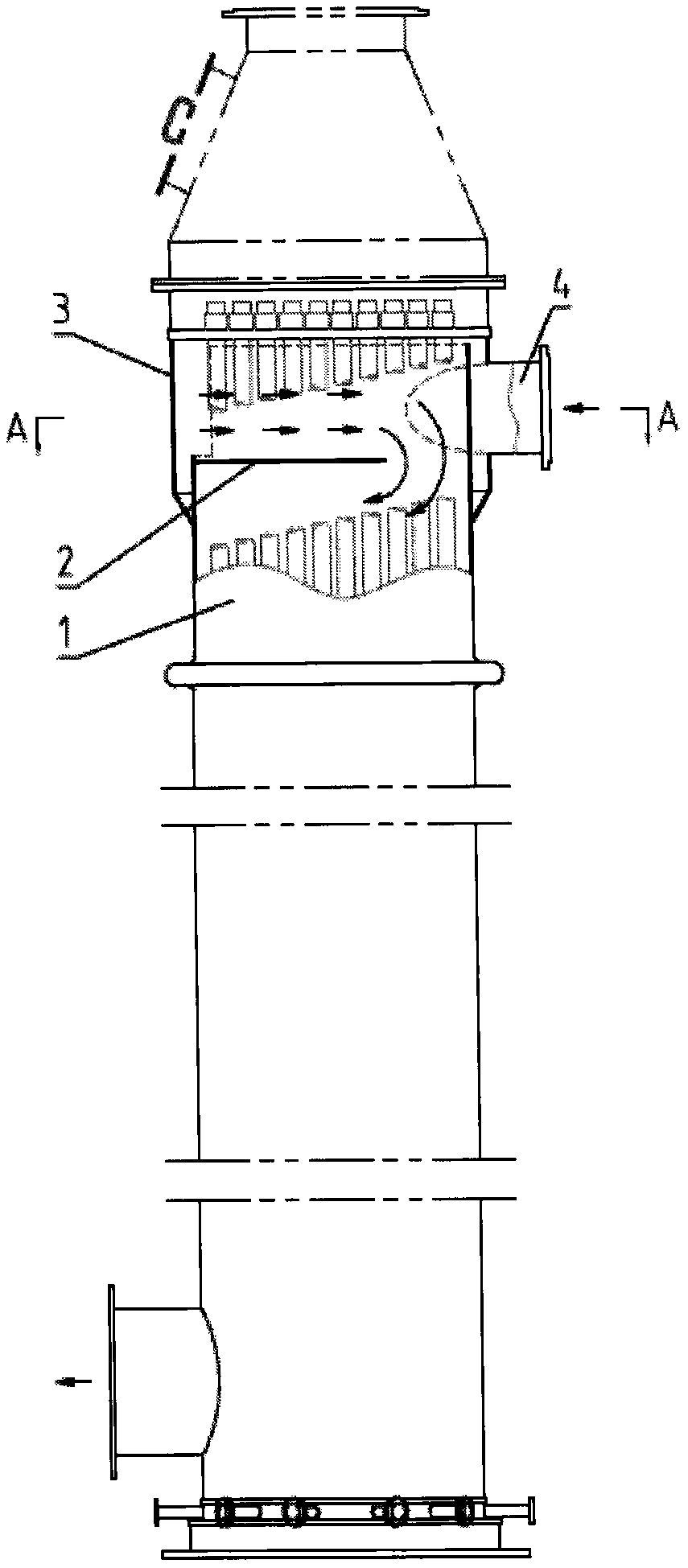
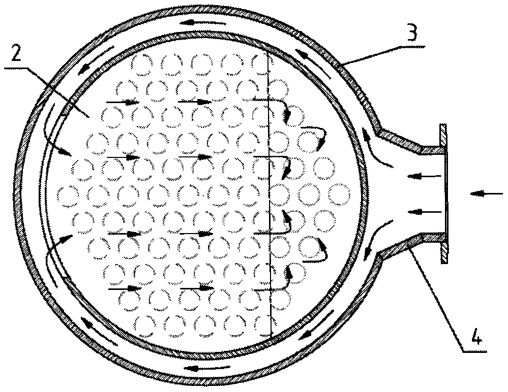
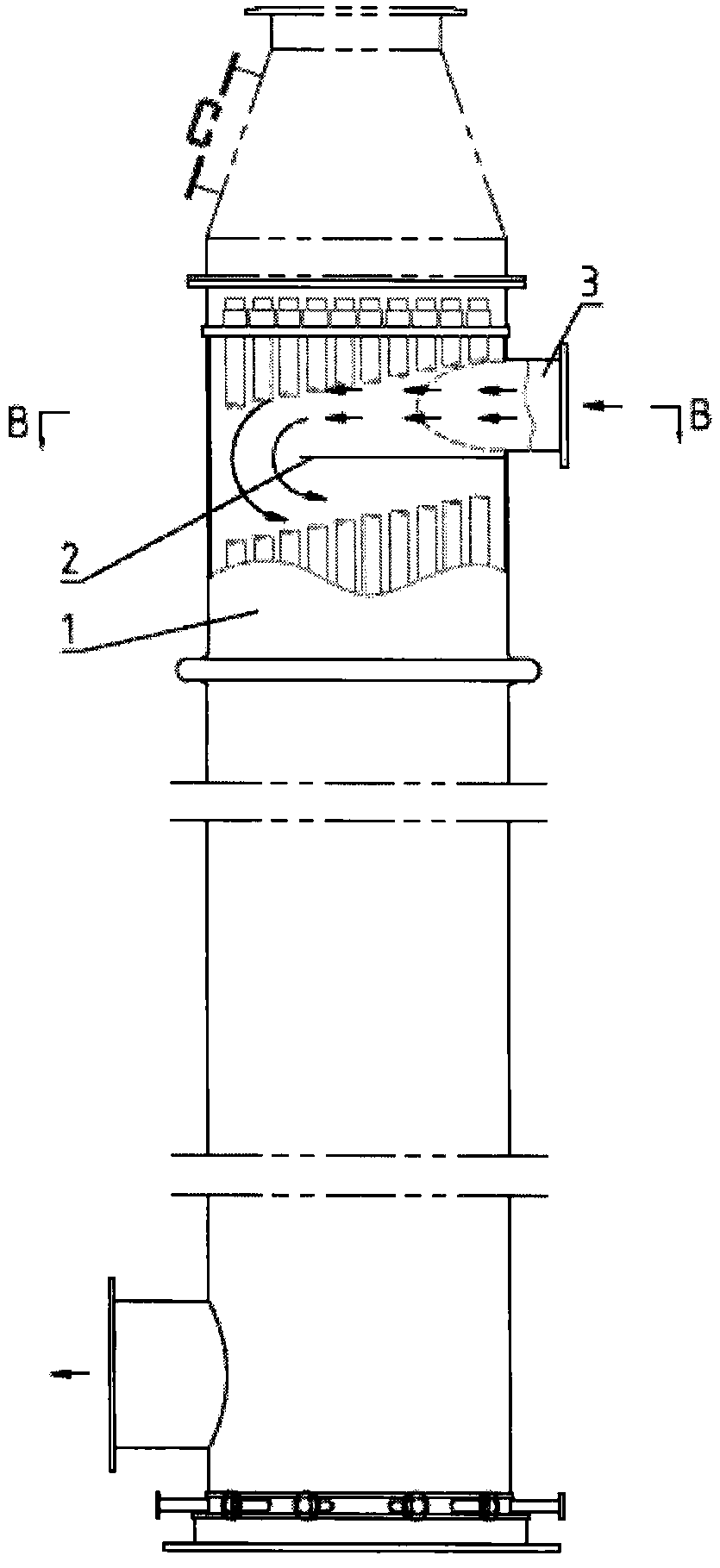
[0028] A shell-and-tube air preheater annular air intake structure comprises: a casing 1 , a baffle 2 , an outer casing 3 , and a cold air inlet 4 . The outer shell 3 and the cold air inlet 4 are assembled and welded, and then a circular hole is opened in the outer shell 3 according to the figure to form the shell-side air inlet structure; the shell 1 and the outer shell 3 are positioned and fixed with a rib plate and then assembled and welded; After exiting the opening position and size of the shell 1, a long opening is opened; the cold air inlet 4 has an opening of 180 degrees with the shell 1, and the baffle plate 2 is adjusted according to the opening direction; the shell 1 and the tube bundle are assembled. Tube sheet assembly welding.

[0029] The annular air inlet structure proposes a new design for the structure of the cold air inlet of the air preheater, which solves the problems of distortion and damage of the tube bundles existing in the air preheater for many years...


PUM


Abstract

The invention discloses a circumferential air inlet structure of a shell-and-tube type air preheater. The circumferential air inlet structure of the shell-and-tube type air preheater is treated as a protective measure performed on a heat exchange tube at an air inlet, and the structure effectively blocks the impact of cold air; the cold air enters a housing pass after being buffered, and the pressure is reduced, and the temperature is improved; the air entering a tube bundle is uniform, and the service life of the air preheater is ensured. The structure comprises a housing, a baffle plate, anouter housing and a cold air inlet, wherein after the outer housing and a cold air inlet connecting pipe are mounted and welded, and a circular hole is formed in the outer housing, so that a shell-pass air inlet structure is formed; the housing and the outer housing are positioned and fixed through a rib plate and then are subjected to mounting and welding; an opening of the housing is a long opening; the cold air inlet connecting pipe and the housing are opened in 180 degrees; the baffle plate is correspondingly adjusted and arranged based on the opening direction; and after the housing and apipe bundle are assembled, the outer housing and an upper tube plate are mounted and welded.

Description

technical field [0001] The invention relates to a shell-and-tube air preheater, wherein the tube side is high-temperature flue gas, and the shell side is air. The cold air enters the shell side from the cold air inlet of the upper part of the shell of the heat exchange section and exchanges heat with the high temperature flue gas entering the tube side, and then flows out from the lower hot air outlet. The cold air directly enters the shell and passes through the tube bundle under the guidance of the baffle plate to achieve contact with the tube bundle to absorb the surface heat of the heat exchange tube, so as to achieve the purpose of heating the air. The cold air with a certain pressure enters the shell and blows directly on the tube bundle near the inlet, which will impact the heat exchange tube at this position. Compared with the heat exchange tubes at other positions, the cooling temperature difference is larger. The heat exchange tube is easily deformed and damaged. T...

Claims


Application Information

Patent Timeline
IPC IPC(8): F23L15/04F28F9/00
CPCF23L15/04F28F9/00Y02E20/34
Inventor 吕宏霞金延超李炳仁
Owner DORIGHT
Why Eureka
Try Eureka