Equipment positioning method and system in visible light communication

A technology of visible light communication and positioning method, applied in the field of device positioning method and system in visible light communication, can solve the problems of low camera resolution, unable to obtain position estimation, difficult to obtain accurate position, etc., and achieve the effect of high positioning accuracy

Inactive Publication Date: 2019-12-10
TSINGHUA UNIV
View PDF3 Cites 6 Cited by
  • Summary
  • Abstract
  • Description
  • Claims
  • Application Information

AI Technical Summary

Problems solved by technology

However, since most of the current cameras are digital cameras, it is difficult to accurately obtain the image point coordinates of the LED. Therefore, when the resolution of the camera is low or the distance from the LED source is too far, it is difficult to obtain an accurate position or even a position estimate. At the same time, the positioning accuracy will be affected. Influence of camera focal length, lens diopter and other parameters

Method used


Image

  • Equipment positioning method and system in visible light communication
  • Equipment positioning method and system in visible light communication
  • Equipment positioning method and system in visible light communication

Examples


Embodiment Construction

[0039] In order to make the purpose, technical solutions and advantages of the embodiments of the present invention clearer, the technical solutions in the embodiments of the present invention will be clearly and completely described below in conjunction with the drawings in the embodiments of the present invention. Obviously, the described embodiments It is a part of embodiments of the present invention, but not all embodiments. Based on the embodiments of the present invention, all other embodiments obtained by persons of ordinary skill in the art without creative efforts fall within the protection scope of the present invention.

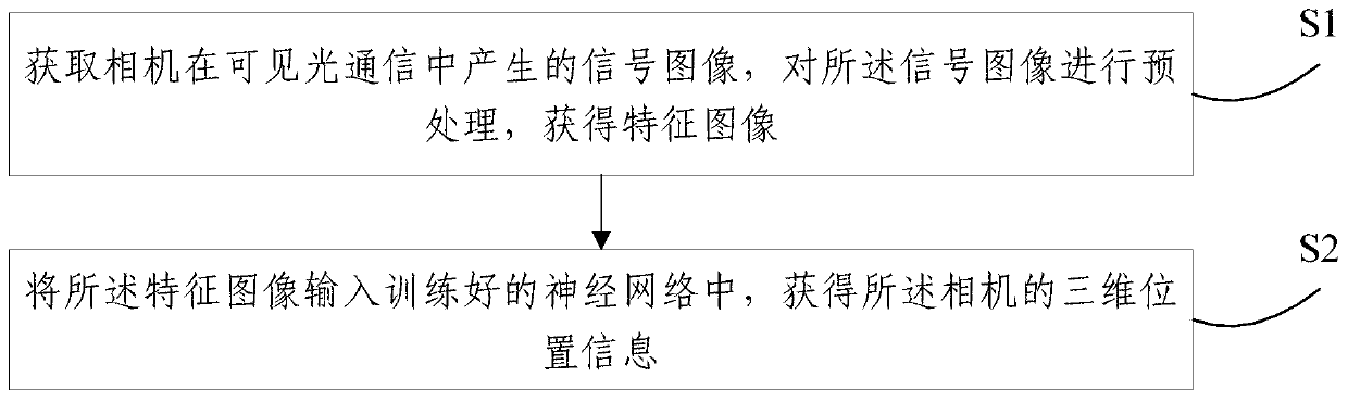
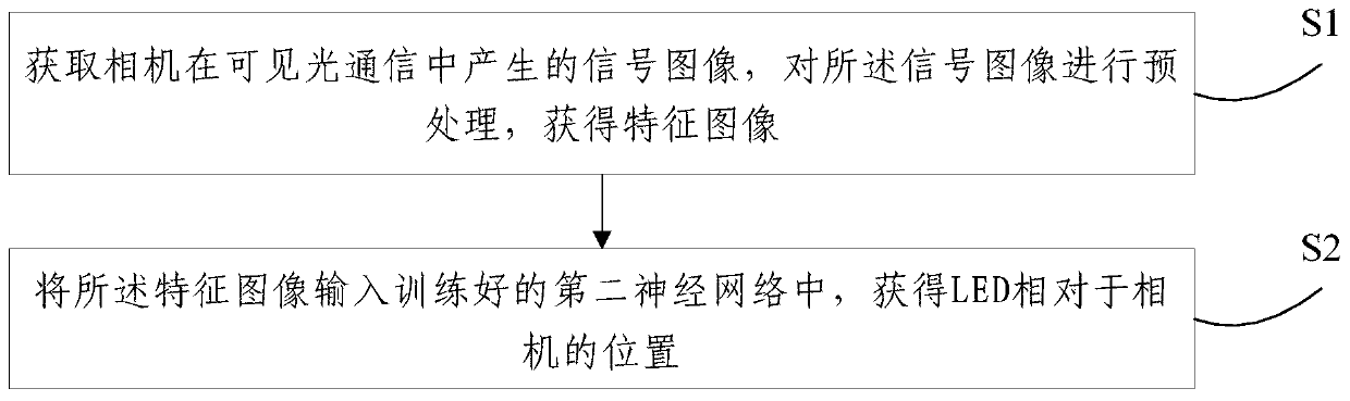
[0040] refer to figure 1 , figure 1 It is a schematic flowchart of a device positioning method in visible light communication provided by an embodiment of the present invention, and the provided method includes:

[0041] S1. Acquire a signal image generated by a camera in visible light communication, and perform preprocessing on the signal image...


PUM


Abstract

The embodiment of the invention provides equipment positioning method and system in visible light communication, wherein the method comprises the steps: obtaining a signal image generated by a camerain the visible light communication, carrying out the preprocessing of the signal image, and obtaining a feature image; inputting the feature image into a trained neural network to obtain three-dimensional position information of the camera, wherein the three-dimensional position information of the camera comprises, but is not limited to, one or a combination of camera position information and a camera inclination angle. According to the method and the system provided by the embodiment of the invention, the trained neural network is adopted to position the camera in the visible light communication system, and compared with a traditional geometric method, higher positioning precision can be realized under the same resolution, and meanwhile, the influence by the height of the camera is relatively small.

Description

technical field [0001] The present invention relates to the field of computer technology, in particular to a device positioning method and system in visible light communication. Background technique [0002] With the explosive growth of mobile communication users, traditional radio frequency communication has gradually been unable to meet the communication needs, and visible light communication (Visible Light Communication, VLC) has attracted widespread attention due to its high speed, low power consumption, high security and strong applicability. attention of researchers. Visible light communication has great potential in short-distance communication scenarios such as indoor communication, vehicle communication, and the Internet of Things. In these communication scenarios, there is an increasing demand for Location-Base Service (LBS), such as intelligent driving, indoor navigation, and behavior detection. Since the signal is mainly transmitted through the LOS path in the ...

Claims


Application Information

Patent Timeline
Patent Type & Authority Applications(China)
IPC IPC(8): G01S5/16H04B10/116H04B10/67H04B10/69H04N5/232G06T7/73
CPCG01S5/16H04B10/116H04B10/67H04B10/69G06T7/73G06T2207/10012G06T2207/20081G06T2207/20084H04N23/80
Inventor 王昭诚刘沛玺赵培尧
Owner TSINGHUA UNIV
Why Eureka
Try Eureka