Valve train for engine and vehicle having same

A valve mechanism and engine technology, applied in the direction of engine components, machines/engines, mechanical equipment, etc., can solve the problems of not being able to adapt to the operating conditions of the engine at the same time, not being able to adjust the law of valve movement, and unfavorable engine power performance, etc., to improve low speed Torque and transient operating response characteristics, extended valve opening duration, and compact structure

Active Publication Date: 2017-07-28
GREAT WALL MOTOR CO LTD
View PDF7 Cites 0 Cited by
  • Summary
  • Abstract
  • Description
  • Claims
  • Application Information

AI Technical Summary

Problems solved by technology

However, due to the single cam profile, it is impossible to adjust the valve movement law according to the actual working conditions of the engine, and it cannot adapt to different operating conditions of the engine at the same time, resulting in high fuel consumption and poor emissions. The advanced variable valve lift technology can only change the maximum lift of the valve opening, the change method is relatively simple, and the structure is complex, there are many parts, and the control is cumbersome

Method used


Image

  • Valve train for engine and vehicle having same
  • Valve train for engine and vehicle having same
  • Valve train for engine and vehicle having same

Examples


Embodiment Construction

[0049] Embodiments of the present invention are described in detail below, examples of which are shown in the drawings, wherein the same or similar reference numerals designate the same or similar elements or elements having the same or similar functions throughout. The embodiments described below by referring to the figures are exemplary and are intended to explain the present invention and should not be construed as limiting the present invention.

[0050] In describing the present invention, it should be understood that the terms "center", "longitudinal", "transverse", "length", "width", "thickness", "upper", "lower", "front", " Orientation or position indicated by "back", "left", "right", "vertical", "horizontal", "top", "bottom", "inner", "outer", "clockwise", "counterclockwise", etc. The relationship is based on the orientation or positional relationship shown in the drawings, and is only for the convenience of describing the present invention and simplifying the descrip...


PUM


Abstract

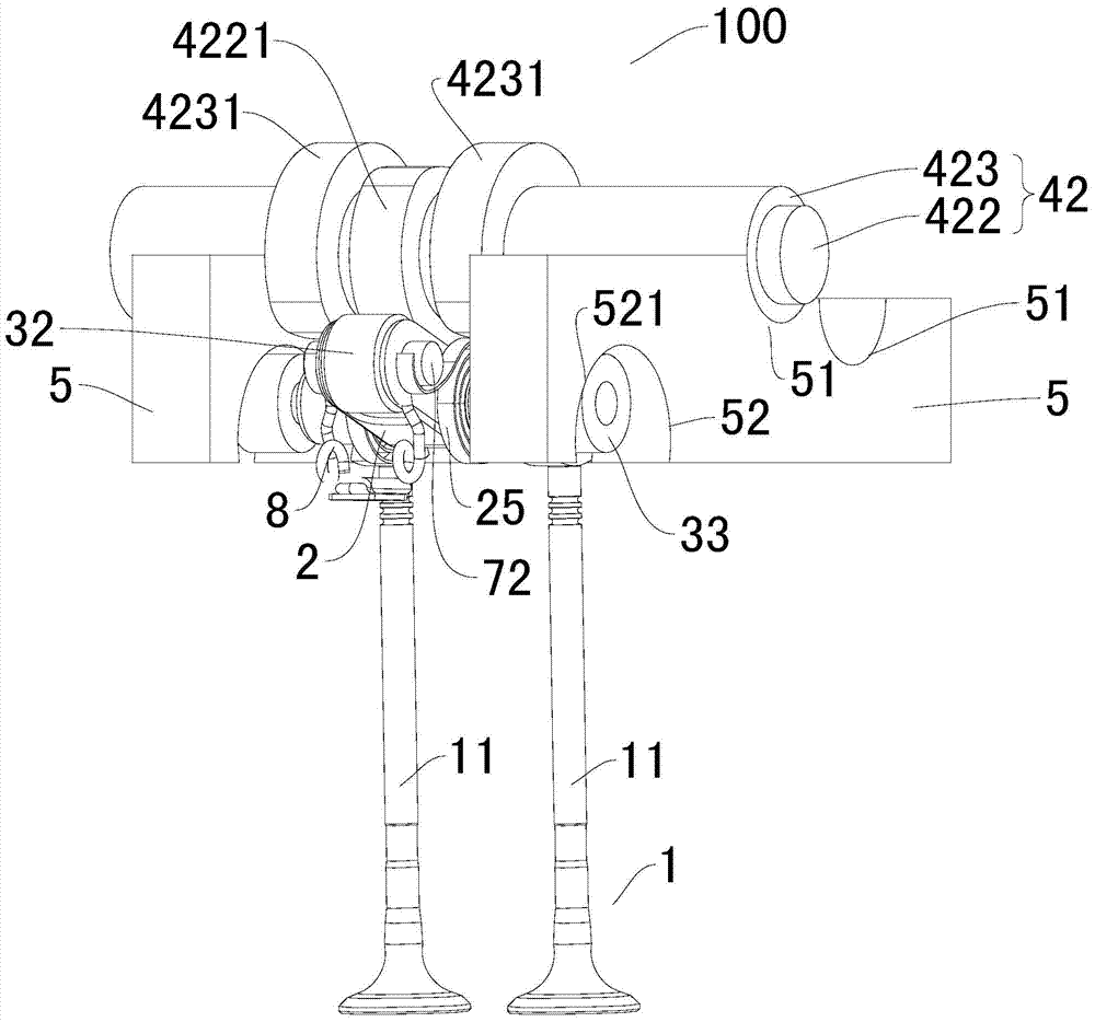
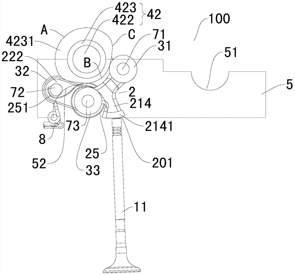
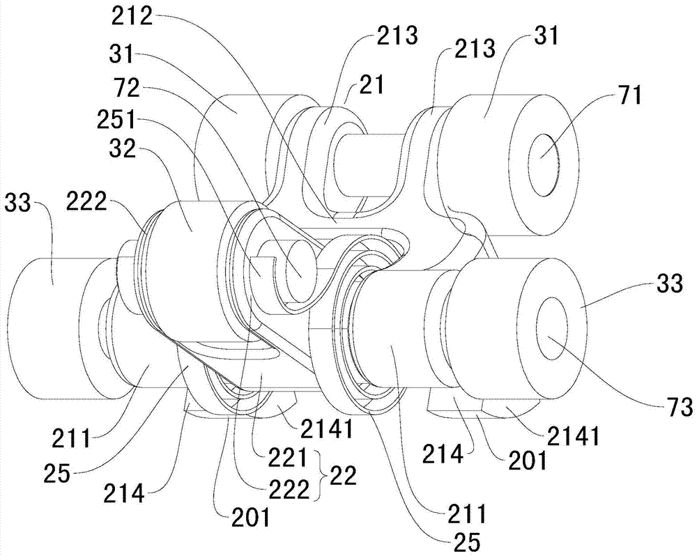
The invention discloses a valve mechanism for an engine and a vehicle comprising the valve mechanism. The valve mechanism comprises a valve mechanism body, a rocker component, a first roller, a second roller, a camshaft, supporting structures, a phase adjusting mechanism, and a third roller or limit pins. The bottom of the rocker component is provided with a drive molded surface which is suitable for directly driving a valve to move. The first roller and the second roller both can be arranged on the rocker component in a pivoting mode. The camshaft comprises an inner shaft and an outer shaft, the inner shaft and the outer shaft are coaxially arranged and provided with an inner shaft cam and an outer shaft cam respectively, and the inner shaft cam and the outer shaft cam can rotate along the corresponding shafts respectively. The outer shaft cam abuts against the first roller, the inner shaft cam abuts against the second roller, the supporting structures are arranged on the two sides of the rocker component and provided with circular arc cambers or sliding grooves, the third roller can be attached to the circular arc cambers in a rolling mode, and the limit pins can be matched in the sliding grooves in a sliding mode. The valve mechanism can achieve secondary opening of the valve, can lengthen the opening lasting time of the valve, and is simple in structure, and low in influence on the height of the engine.

Description

technical field [0001] The invention relates to the field of automobile construction, in particular to a gas distribution mechanism for an engine and a vehicle with the same. Background technique [0002] The valve mechanism of the engine is used to drive the opening and closing of the valves. The valve timing is generally determined based on the local optimization of a narrow working range of the engine. It is fixed during the working process, and the valve movement law is completely determined by the cam profile. . However, due to the single cam profile, it is impossible to adjust the valve movement law according to the actual working conditions of the engine, and it cannot adapt to different operating conditions of the engine at the same time, resulting in high fuel consumption and poor emissions. The advanced variable valve lift technology can only change the maximum lift of the valve opening, the change method is relatively simple, and the structure is complex, there a...

Claims


Application Information

Patent Timeline
Patent Type & Authority Patents(China)
IPC IPC(8): F01L13/00
Inventor 桂小林张金龙朱涛王双龙韩泽明王斌王建中
Owner GREAT WALL MOTOR CO LTD
Why Eureka
Try Eureka