Image lens and image capturing device

一种镜头、影像的技术,应用在光学元件、光学、仪器等方向,能够解决难以兼具大视角与短总长、难以搭载电子装置等问题

Active Publication Date: 2019-12-10
LARGAN PRECISION
View PDF4 Cites 3 Cited by
  • Summary
  • Abstract
  • Description
  • Claims
  • Application Information

AI Technical Summary

Problems solved by technology

However, it is difficult for existing image lenses to meet the requirements of large viewing angle and short overall length, so it is difficult to be mounted on relatively thin and light electronic devices

Method used


Image

  • Image lens and image capturing device
  • Image lens and image capturing device
  • Image lens and image capturing device

Examples


no. 1 example

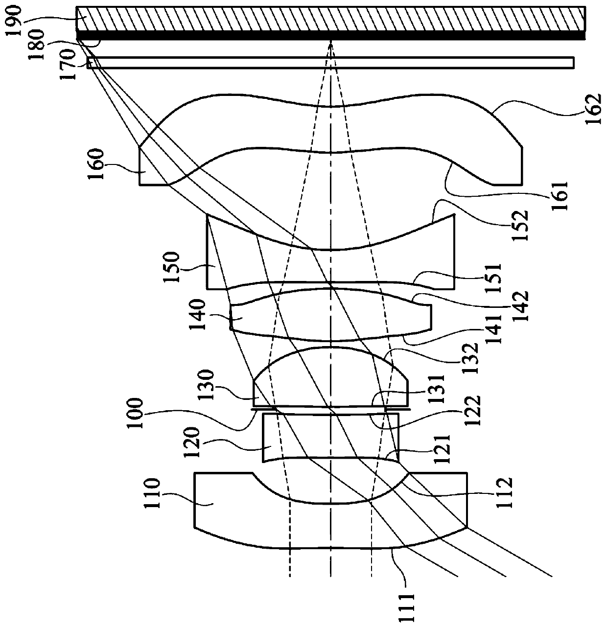
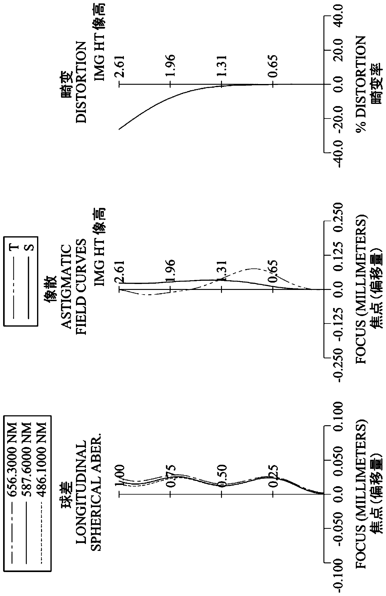
[0142] Please refer to figure 1 and figure 2 ,in figure 1 A schematic diagram of an imaging device according to a first embodiment of the present invention is shown, figure 2 From left to right are the spherical aberration, astigmatism and distortion curves of the first embodiment. Depend on figure 1 It can be seen that the image capturing device includes an image lens (not labeled separately) and an electronic photosensitive element 190 . The imaging lens includes first lens 110, second lens 120, aperture 100, third lens 130, fourth lens 140, fifth lens 150, sixth lens 160, and infrared filter elements in order from the object side to the image side. (IR-cut Filter) 170 and imaging surface 180 . Wherein, the electronic photosensitive element 190 is disposed on the imaging surface 180 . The lenses (110-160) of the image lens are six single and non-cemented lenses.

[0143] The first lens 110 has negative refractive power and is made of plastic material. Its object-sid...

no. 2 example

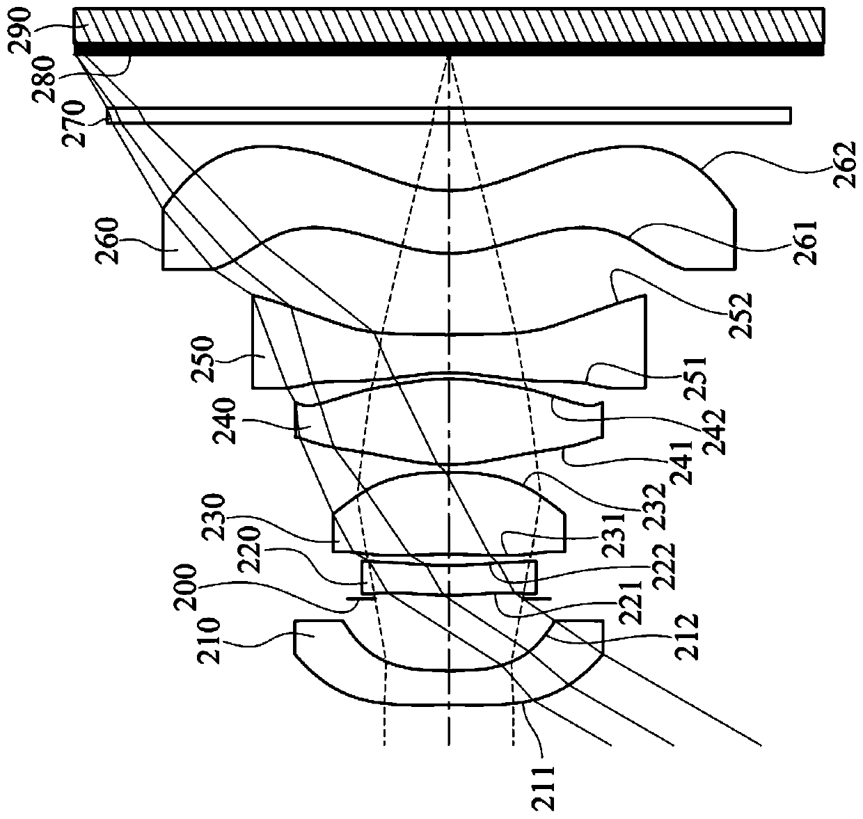
[0182] Please refer to image 3 and Figure 4 ,in image 3 A schematic diagram of an imaging device according to a second embodiment of the present invention is shown, Figure 4 From left to right are the spherical aberration, astigmatism and distortion curves of the second embodiment. Depend on image 3 It can be seen that the image capturing device includes an image lens (not labeled separately) and an electronic photosensitive element 290 . The imaging lens includes a first lens 210, an aperture 200, a second lens 220, a third lens 230, a fourth lens 240, a fifth lens 250, a sixth lens 260, and an infrared filter element in order from the object side to the image side. 270 and imaging surface 280 . Wherein, the electronic photosensitive element 190 is disposed on the imaging surface 180 . The lenses (210-260) of the image lens are six single and non-cemented lenses.

[0183] The first lens 210 has negative refractive power and is made of plastic material. Its object-...

no. 3 example

[0197] Please refer to Figure 5 and Figure 6 ,in Figure 5 A schematic diagram of an imaging device according to a third embodiment of the present invention is shown, Figure 6 From left to right are the spherical aberration, astigmatism and distortion curves of the third embodiment. Depend on Figure 5 It can be seen that the image capturing device includes an image lens (not another number) and an electronic photosensitive element 390 . The imaging lens includes a first lens 310, an aperture 300, a second lens 320, an aperture 301, a third lens 330, a fourth lens 340, a fifth lens 350, a sixth lens 360, and an infrared filter from the object side to the image side. Except the filter element 370 and the imaging surface 380 . Wherein, the electronic photosensitive element 390 is disposed on the imaging surface 380 . The lenses (310-360) of the image lens are six single and non-cemented lenses. The diaphragm 301 is, for example, a flare diaphragm or a field diaphragm. ...


PUM


Abstract

An image lens is disclosed and includes, in order from an object side to an image side, a first lens element, a second lens element, a third lens element, a fourth lens element, a fifth lens element and a sixth lens element. The first lens element has negative refractive power. The third lens element has positive refractive power. The fourth lens element has positive refractive power. The fifth lens element has negative refractive power, the image-side surface of the fifth lens element is concave in a paraxial region thereof and an object-side surface and the image-side surface are aspheric. The sixth lens element has an image-side surface being concave in a paraxial region thereof, the image-side surface has at least one inflection point in an off-axis region thereof, and both of the object-side surface and the image-side surface of the sixth lens element are aspheric. The total number of lenses of the image lens is six. When specific conditions are met, the image lens can meet the requirements of a large viewing angle, high imaging quality and miniaturization at the same time.

Description

[0001] This application is a divisional application. The filing date of the original application is: August 26, 2016; the application number is: 201610728907.9; the title of the invention is: video lens, imaging device and electronic device. technical field [0002] The invention relates to an image lens, an image capturing device and an electronic device, in particular to an image lens and an image capturing device suitable for the electronic device. Background technique [0003] In recent years, with the vigorous development of miniaturized photographic lenses, the demand for miniature imaging modules has increased day by day, and with the advancement of semiconductor technology, the pixel size of photosensitive elements has been reduced. The short appearance is the development trend. Therefore, miniaturized photographic lenses with good imaging quality have become the mainstream in the current market. [0004] As the application of camera modules becomes more and more ex...

Claims


Application Information

Patent Timeline
Patent Type & Authority Applications(China)
IPC IPC(8): G02B13/00G02B13/06G02B13/18
CPCG02B13/0045G02B13/06G02B13/18
Inventor 薛钧哲陈纬彧
Owner LARGAN PRECISION
Why Eureka
Try Eureka