Fiber output terminal and laser device

A technology of output terminals and lasers, which is applied in the field of optical fibers, can solve the problems that the fiber core protection cannot achieve the effect of water leakage.

Pending Publication Date: 2019-12-10
SHENZHEN SUPER LASER TECH
View PDF0 Cites 0 Cited by
  • Summary
  • Abstract
  • Description
  • Claims
  • Application Information

AI Technical Summary

Problems solved by technology

[0004] This application provides an optical fiber output terminal and a laser to solve the problem in the prior art that direct glue filling inside the fiber core protection can not achieve a better water leakage effect

Method used


Image

  • Fiber output terminal and laser device
  • Fiber output terminal and laser device
  • Fiber output terminal and laser device

Examples


Embodiment Construction

[0015] The technical solutions in the embodiments of the present application will be clearly and completely described below in conjunction with the drawings in the embodiments of the present application. It should be understood that the specific embodiments described here are only used to explain the present application, but not to limit the present application. In addition, it should be noted that, for the convenience of description, only some structures related to the present application are shown in the drawings but not all structures. Based on the embodiments in this application, all other embodiments obtained by persons of ordinary skill in the art without creative efforts fall within the protection scope of this application.

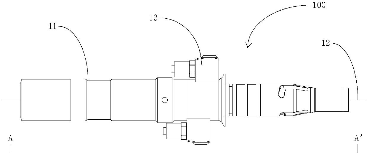
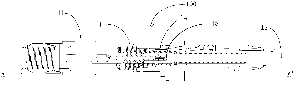
[0016] See figure 1 and figure 2 , figure 1 It is a schematic structural diagram of Embodiment 1 of the optical fiber output terminal of the present application; figure 2 yes figure 1 The cross-sectional schematic diagram of the optical fibe...


PUM


Abstract

The invention provides a fiber output terminal and a laser device. The fiber output terminal comprises a main body, a fiber, a fiber core water-cooling piece and a fiber core protection piece, whereinthe fiber core water-cooling piece is sleeved in the main body, the fiber core protection piece is sleeved in the fiber core water-cooling piece, the fiber is arranged in the fiber core protection piece, the fiber core protection piece is used for protecting the fiber, a sealing piece is arranged at one end of the fiber core protection piece close to the fiber core water-cooling piece, and the sealing piece is used for preventing the water in the fiber core water-cooling piece from entering the fiber core protection piece. The fiber output terminal is advantaged in that the sealing piece is arranged at one end of the fiber core protection piece, the water leakage prevention effect of the fiber output terminal can be effectively ensured, and the product yield is improved.

Description

technical field [0001] The present application relates to the field of optical fiber, in particular to an optical fiber output terminal and a laser. Background technique [0002] At present, the power of the light source output by the laser is continuously increasing. While the output power is increasing, the surface temperature of the optical fiber is also increasing. Due to the design consideration of protecting the optical fiber, in the prior art, a water cooling structure is added to the output terminal of the optical fiber, so as to reduce the surface temperature of the optical fiber. [0003] Since the existing technology is to directly pour glue into the fiber core protector which is installed in a water-cooled structure, firstly, the way of direct glue filling is easy to cause loss to the optical fiber of the fiber core protector; secondly, the glue will be in the fiber core protector Fast solidification, if the glue pouring speed is slow, it will cause the glue to...

Claims


Application Information

Patent Timeline
Patent Type & Authority Applications(China)
IPC IPC(8): H01S5/024H01S5/022
CPCH01S5/022H01S5/02423
Inventor 李云丰
Owner SHENZHEN SUPER LASER TECH
Why Eureka
Try Eureka