Centrifugal granular fertilizer spreader

A granular fertilizer and centrifugal technology, applied in the field of agricultural machinery, can solve the problems of staying, reducing labor intensity, uneven fertilizer application, etc., and achieve the effect of smooth fertilizer spreading process, improving work efficiency and reducing labor intensity

Inactive Publication Date: 2019-12-13
LUAN YONGZHEN GRIZZLY ELECTRICAL & MECHANICAL TECH CO LTD
View PDF9 Cites 0 Cited by
  • Summary
  • Abstract
  • Description
  • Claims
  • Application Information

AI Technical Summary

Problems solved by technology

[0002] Granular fertilizers are generally artificially synthesized fertilizers with high nutrient content, and the amount of application per unit area of ​​land is limited. Therefore, it is very important to spread them evenly into the land during application. There are two extremes in application, and some are still at the stage of manual application. Most of the equipment developed by research and development is complicated in structure, high in cost, and there are many supporting tools for farming, so it is difficult to popularize. There are also relatively simple and practical application tools. The structure is The spreading disc under the fertilizer bucket is driven by the walking wheels to scatter around. As a result, the equipment is repeatedly spread before and after the equipment, resulting in about twice as much land before and after the equipment as compared with the left and right sides. There are also places where the equipment is poured into the fertilizer bucket and the tractor is on the ground. When turning to work, a lot of fertilizer will flow out, resulting in very uneven fertilizer application. Therefore, the inventor designed a granular fertilizer spreading equipment, which can evenly spread granular fertilizer outward, and the entire spreading process is fully automated, without the need for staff to manually operation, greatly reducing labor intensity and improving work efficiency

Method used


Image

  • Centrifugal granular fertilizer spreader
  • Centrifugal granular fertilizer spreader
  • Centrifugal granular fertilizer spreader

Examples


Embodiment Construction

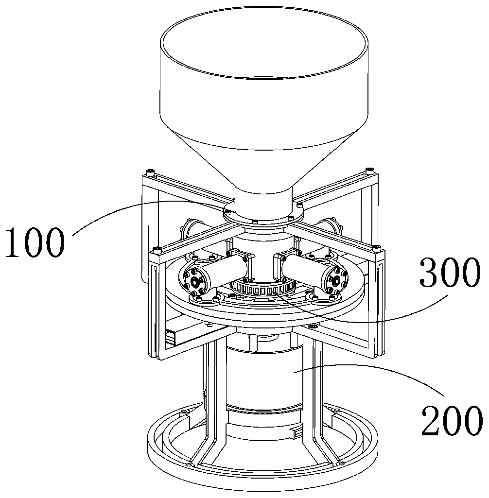
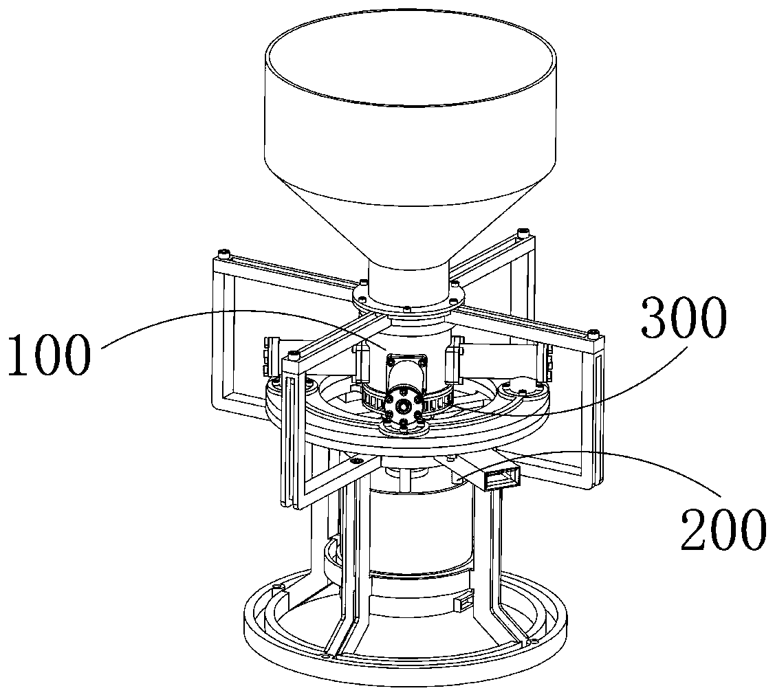
[0050] The present invention adopts the high-speed rotating centrifugal throwing method to throw the granular fertilizer. The advantage is that the staff only need to pour the granular fertilizer into the feeding funnel, and the granular fertilizer can be evenly spread outward through the auger mechanism and the centrifugal throwing device. Spreading, the entire spreading process is fully automated, without manual operation by staff, which greatly reduces labor intensity and improves work efficiency. At the same time, the auger feeding device and the centrifugal spreading device share the same power source, and the power deceleration transmission device is used between the two The power transmission prevents the auger feeding device from feeding too fast and blocking the material receiving hole, and the fertilizer spreading process is smoother. In addition, the four groups of cavity walls of the throwing cylinder are all equipped with dispersing protrusions, which can The ferti...


PUM


Abstract

The invention provides a centrifugal granular fertilizer spreader. The centrifugal granular fertilizer spreader comprises a mounting frame body, an auger feeding device, a centrifugal spreading deviceand a power deceleration transmission device, wherein the mounting frame body is arranged on agriculture advancing equipment such as a tractor, the auger feeding device, the centrifugal spreading device and the power deceleration transmission device are all arranged on the mounting frame body, the auger feeding device is used for conveying a granular fertilizer into the centrifugal spreading device by means of auger conveying, the centrifugal spreading device is used for spreading the granular fertilizer by means of high-speed rotation centrifugation, and the power deceleration transmission device is used for receiving power of the centrifugal spreading device, conducting deceleration treatment on the power and transmitting the power to the auger feeding device. A worker only needs to pour the granular fertilizer into a feeding hopper, the granular fertilizer can be automatically and uniformly spread outward through an auger mechanism and the centrifugal spreading device, the whole spreading process is completely automatic, and the worker does not need to perform manual operation, thereby greatly reducing the labor intensity and improving the work efficiency.

Description

technical field [0001] The invention relates to the field of agricultural machinery, in particular to a granular fertilizer spreading device. Background technique [0002] Granular fertilizers are generally artificially synthesized fertilizers with high nutrient content, and the amount of application per unit area of ​​land is limited. Therefore, it is very important to spread them evenly into the land during application. There are two extremes in application, and some are still at the stage of manual application. Most of the equipment developed by research and development is complicated in structure, high in cost, and there are many supporting tools for farming, so it is difficult to popularize. There are also relatively simple and practical application tools. The structure is The spreading disc under the fertilizer bucket is driven by the walking wheels to scatter around. As a result, the equipment is repeatedly spread before and after the equipment, resulting in about twi...

Claims


Application Information

Patent Timeline
IPC IPC(8): A01C17/00F16H1/32
CPCA01C17/001A01C17/005F16H1/32F16H2001/327
Inventor 潘声田张冠周瑞
Owner LUAN YONGZHEN GRIZZLY ELECTRICAL & MECHANICAL TECH CO LTD
Why Eureka
Try Eureka