
Environmental protection slipper spin-drying device

A technology for slippers and equipment, applied in the field of environmental protection slippers drying equipment, can solve the problems of small washing machine capacity, waste, environmental pollution, etc., achieve the effect of large drying box space, high degree of automation, and reduce garbage pollution

Pending Publication Date: 2019-12-13
杭州杜尚美环保科技有限公司
View PDF0 Cites 0 Cited by
  • Summary
  • Abstract
  • Description
  • Claims
  • Application Information

AI Technical Summary

Problems solved by technology

Therefore, the consumption of disposable slippers is very large, and these disposable slippers are discarded after use, which not only causes environmental pollution and domestic garbage, but also brings a certain degree of waste. Therefore, environmentally friendly slippers are widely accepted. It is popular in the market, but at present, almost all public places such as guest houses, restaurants, hotels, public baths, etc. basically do not have special drying facilities for environmental protection slippers. As we all know, the existing washing machines can dry clothes, and the drying of clothes depends on The most important thing is that the centrifugal force generated by the high-speed rotating drying barrel separates the water from the clothes. When the drying barrel is working, the clothes are attached to the inner wall of the drying barrel
Then when using a washing machine to dry shoes, the shoes are attached to the inner wall, and the capacity of the washing machine is small. In the prior art, there is no special shoe drying machine. The dehydration methods of shoes are generally sun drying or natural air drying. It takes a long time to complete the cleaning of multiple pairs of slippers, and it cannot be installed in the environmental protection slippers washing, drying and drying process line

Method used


Image

  • Environmental protection slipper spin-drying device
  • Environmental protection slipper spin-drying device
  • Environmental protection slipper spin-drying device

Examples


Embodiment Construction

[0023] The following will clearly and completely describe the technical solutions in the embodiments of the present invention with reference to the accompanying drawings in the embodiments of the present invention. Obviously, the described embodiments are only some, not all, embodiments of the present invention. Based on the embodiments of the present invention, all other embodiments obtained by persons of ordinary skill in the art without making creative efforts belong to the protection scope of the present invention.

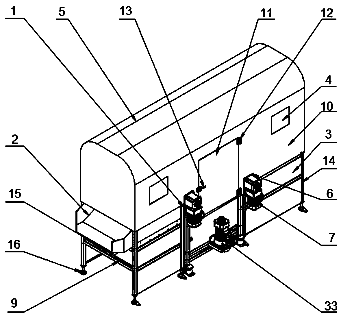
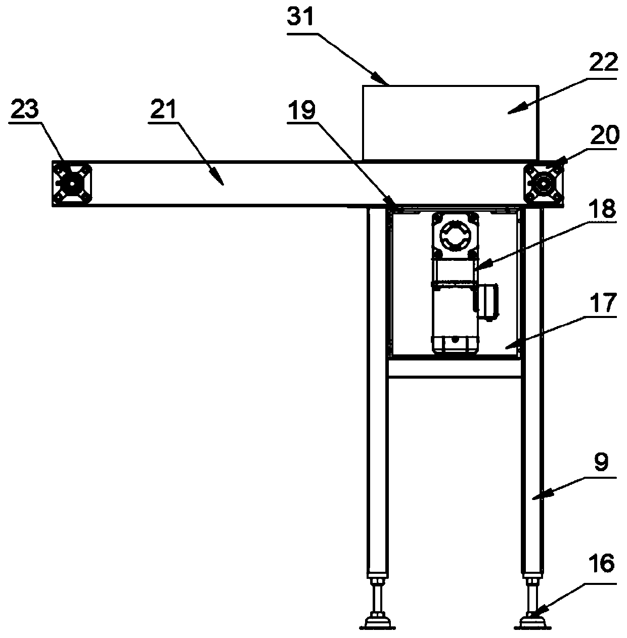
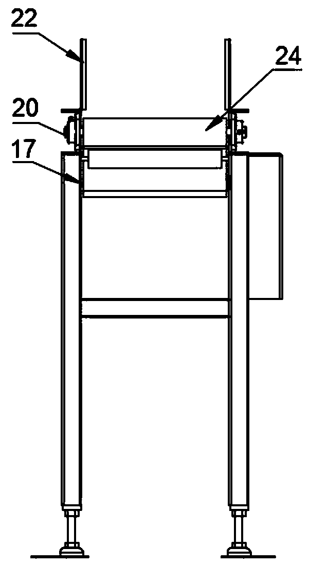
[0024] see Figure 1-7 , the present invention provides a technical solution: a drying equipment for environmentally friendly slippers, including a drying box 5, a transition wire frame 9 and a drying frame 14, and the drying box 5 is fixedly installed on the transition wire frame 9 and the drying frame 14, the outer end surface of the drying box 5 is welded with a drying cover 10, and the transition line frame 9 and the drying frame 14 outer ends are fixed wi...


PUM


Abstract

The invention discloses an environmental protection slipper spin-drying device. The environmental protection slipper spin-drying device comprises a spin-drying box, a transition wire rack and a spin-drying rack; the spin-drying box is fixedly installed on the transition wire rack and the spin-drying rack; a spin-drying outer cover is welded to the outer end surface of the spin-drying box; an outercover plate is fixed to the outer end of the transition wire rack and the spin-drying rack; a spin-drying outer cover door is movably provided on the outer end surface of the spin-drying box throughhinges; an air-tight handle is arranged on the spin-drying outer cover door; motor mounting seats are installed on both sides of the spin-drying outer cover door; a spin-drying motor is fixedly installed on each motor mounting seat; a spin dryer is rotatably connected to the rotation output shaft of each spin-drying motor; a motor is arranged below the spin-drying outer cover door; the motor rotation output end is connected with a receiving box through a rotating shaft; a transition belt wire is arranged on one side of the spin dryer; and a side plate is arranged on the transition belt wire. The environmental protection slipper spin-drying device has high work efficiency and high degree of automation, and is suitable for wide promotion.

Description

technical field [0001] The invention relates to a spin-drying device, in particular to a spin-drying device for environment-friendly slippers. Background technique [0002] Disposable slippers are commonly used daily necessities in hotels. In addition to hotels and hotels, there are some other public living places and leisure places that also need to use disposable slippers. Under normal circumstances, each guest uses a pair of disposable slippers every day, and the service life of each pair of slippers is only one day. Therefore, the consumption of disposable slippers is very large, and these disposable slippers are discarded after use, which not only causes environmental pollution and domestic garbage, but also brings a certain degree of waste. Therefore, environmentally friendly slippers are widely accepted. It is popular in the market, but at present, almost all public places such as guest houses, restaurants, hotels, public baths, etc. basically do not have special dry...

Claims


Application Information

Patent Timeline
Patent Type & Authority Applications(China)
IPC IPC(8): A47L23/00
CPCA47L23/00
Inventor 姜益军
Owner 杭州杜尚美环保科技有限公司
Learn More