Rubber roller on a corrugating machine

A technology for corrugating machines and rubber rollers, applied in the field of corrugating machines, can solve the problems of complex anilox roller process, high processing cost, and high processing difficulty, and achieve the effects of avoiding difficult maintenance, easy replacement, and easy adjustment

Active Publication Date: 2021-03-02
重庆利永纸制品包装有限公司
View PDF11 Cites 0 Cited by
  • Summary
  • Abstract
  • Description
  • Claims
  • Application Information

AI Technical Summary

Problems solved by technology

In practical application, it is found that this method has many shortcomings, mainly in the following aspects: the rubber roller generally used in single-sided corrugating machine is anilox roller, on the one hand, the anilox roller has complicated process and high processing difficulty, which makes The processing cost is high; in addition, due to the processing technology, the precision of the anilox roller after processing is far lower than that of the smooth roller

Method used


Image

  • Rubber roller on a corrugating machine
  • Rubber roller on a corrugating machine
  • Rubber roller on a corrugating machine

Examples


Embodiment 1

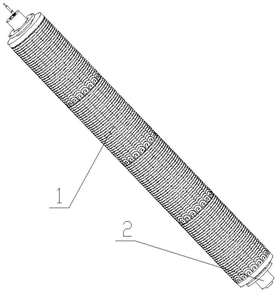
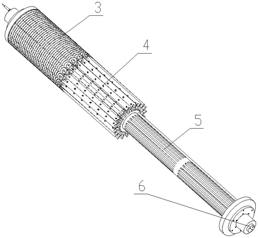
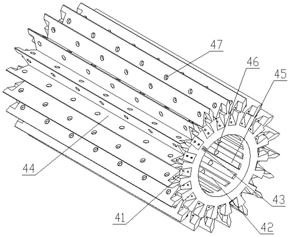
[0029] Such as Figure 1 to Figure 8 As shown; a corrugating machine upper rubber roller, including a glue guiding mechanism 2 and at least one glue applying mechanism 1 sleeved on the glue guiding mechanism 2, the glue applying mechanism 1 communicates with the glue guiding mechanism 2; The glue mechanism 1 includes a glue guide column 4 and a glue block 3 arranged around the glue guide column 4, and the glue block 3 is fixed on the glue guide column 4; the glue guide mechanism 2 includes a dispersed glue guide column 5 and The hot glue delivery column 6, the dispersed glue guide column 5 is set on the hot glue delivery column 6, and the glue outlet of the hot glue delivery column 6 is connected with the dispersed glue guide column 5; Several V-shaped glue grooves 44 are provided, and the glue block 3 is arranged in the V-shaped glue groove 44, and positioning grooves 41 are arranged on the glue guide posts 4 at both ends of the V-shaped glue groove 44; 4 is pierced with a s...

Embodiment 2

[0032]On the basis of Embodiment 1, the dispersing glue guide column 5 is provided with a fixed key 52 and a dispersing glue group 53 connected with the gluing mechanism 1, and the dispersing glue group 53 is composed of several dispersing glue connected to the glue guiding groove 45. Groove 54 is composed of, and the dispersing glue guiding column 5 is penetrated with a hot glue conveying column sleeve hole 51 for the heating glue conveying column 6 to pass through; both ends of the dispersing glue guiding column 5 are provided with a pressure plate 55, and the dispersing glue Both ends of the rubber guide column 5 are connected with a flange bushing 56, the flange bushing 56 includes a flange plate 57 and a bearing sleeve, and the flange plate 57 is provided with a positioning screw hole 58 and a compression screw hole 59, the positioning screw holes 58 and the pressing screw holes 59 are all provided with bolts, the flange plate 57 is connected with the dispersion guide colu...

Embodiment 3

[0036] On the basis of Embodiment 2, the size of the glue outlet 61 can cover at least two dispersion glue grooves 54; a copper sheet with a thickness of at least 0.50mm is arranged between the adjacent glue-up mechanism 1; There is a gap between the arc-shaped rubber separating plates 32, and the gap is 0.05 mm to 0.15 mm; the side of the adjacent arc-shaped rubber separating plates 32 close to the positioning block 31 is in close contact with the adhesive guide column 4; the positioning block 31 is provided with a locking inclined surface 34 near the end of the rubber guide column 4, and a waist-shaped countersunk head is arranged on the locking inclined surface 34, and an inclined surface matching with the locking inclined surface 34 is arranged on the positioning groove 41. There are screw holes.

[0037] By setting the size of the glue outlet 61 to cover at least two dispersion glue grooves 54, the cooperation between the glue outlet 61 and the rotating dispersion glue gr...


PUM

PropertyMeasurementUnit
thicknessaaaaaaaaaa
thicknessaaaaaaaaaa

Abstract

The invention discloses a rubber roller for a corrugating machine, comprising a glue guiding mechanism and at least one glue applying mechanism sleeved on the glue guiding mechanism, the glue applying mechanism is connected with the glue guiding mechanism; the glue applying mechanism includes The glue guide column and the glue block arranged around the glue guide column, the glue block is fixed on the glue guide column; the glue guide mechanism includes a dispersed glue guide column and a hot glue delivery column, and the dispersed glue guide column cover It is arranged on the hot glue conveying column, and the glue outlet of the hot glue conveying column is connected with the dispersed glue guiding column; the rubber roller on a corrugating machine of the present invention passes through the hot glue conveying column, the dispersed glue guiding column and the glue guiding column in sequence It is transported to the surface of the upper rubber block, so that the glue does not need to be attached to the upper rubber roller through the outside of the glue box, saving the installation area of ​​the rubber box and improving the utilization rate of the site; at the same time, the one-way glue output can avoid the situation that the overall glue output of the upper rubber roller is difficult to control. It is convenient to control the amount of glue applied and the degree of uniform bedding of glue.

Description

technical field [0001] The invention belongs to the field of corrugating machines, and in particular relates to a rubber roller on a corrugating machine. Background technique [0002] Corrugated paper is an important paper product. Corrugated board is a plate made of liner paper and corrugated corrugated paper formed by processing corrugated sticks. It is generally divided into two types: single-sided corrugated board and double-sided corrugated board. ; For corrugated cardboard, it has the advantages of low cost, light weight, easy processing, high strength, excellent printing adaptability, convenient storage and transportation, and more than 80% of corrugated cardboard can be recycled; therefore, corrugated cardboard It is widely used in product packaging. [0003] At present, the single-sided corrugating machine generally adopts the following method to apply glue: the rubber roller is in full contact with the glue, after the surface of the rubber roller is covered with g...

Claims


Application Information

Patent Timeline
Patent Type & Authority Patents(China)
IPC IPC(8): B05C1/08B05C1/00
CPCB05C1/003B05C1/0808
Inventor 不公告发明人
Owner 重庆利永纸制品包装有限公司
Why Eureka
Try Eureka