Cooperative three-station extrusion-forging forming equipment

A technology for collaborative work and forming equipment, applied in metal processing equipment, forging presses, forging presses, etc., can solve the problems of hidden dangers of equipment stability, difficult mechanism design, and high equipment height, so as to reduce equipment height and processing difficulty, The effect of avoiding mechanical and electrical failures and improving equipment reliability

Pending Publication Date: 2019-12-13
SUZHOU SANJI FOUNDRY EQUIP
View PDF0 Cites 1 Cited by
  • Summary
  • Abstract
  • Description
  • Claims
  • Application Information

AI Technical Summary

Problems solved by technology

The traditional single-station squeeze casting machine concentrates all the forming processes in one piece of equipment. The injection system is located below the mold. When the mold is cleaned and sprayed, the debris and sewage above will enter the injection system, causing mechanical and electrical failures
The mold clamping system has a large stroke when opening the mold, and the mold opening cylinder needs to drive the middle plate, mold locking cylinder and other components to lift together, which has the disadvantages of high equipment height, complex structure, poor stability, and low efficiency.
For large-scale extrusion molding equipment, the disadvantages of single-station design are particularly prominent, which not only leads to difficulties in mechanism design, but also creates hidden dangers for equipment stability

Method used


Image

  • Cooperative three-station extrusion-forging forming equipment
  • Cooperative three-station extrusion-forging forming equipment
  • Cooperative three-station extrusion-forging forming equipment

Examples


Embodiment Construction

[0022] The following will clearly and completely describe the technical solutions in the embodiments of the present invention with reference to the accompanying drawings in the embodiments of the present invention. Obviously, the described embodiments are only some, not all, embodiments of the present invention. The components of the embodiments of the invention generally described and illustrated in the figures herein may be arranged and designed in a variety of different configurations. Accordingly, the following detailed description of the embodiments of the invention provided in the accompanying drawings is not intended to limit the scope of the claimed invention, but merely represents selected embodiments of the invention. Based on the embodiments of the present invention, all other embodiments obtained by those skilled in the art without making creative efforts belong to the protection scope of the present invention.

[0023] It should be noted that like numerals and let...


PUM


Abstract

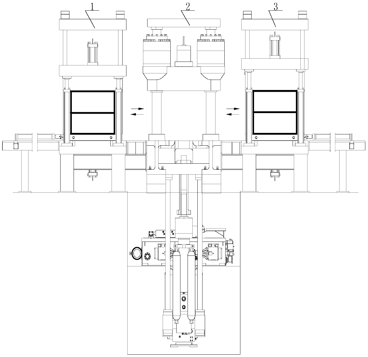
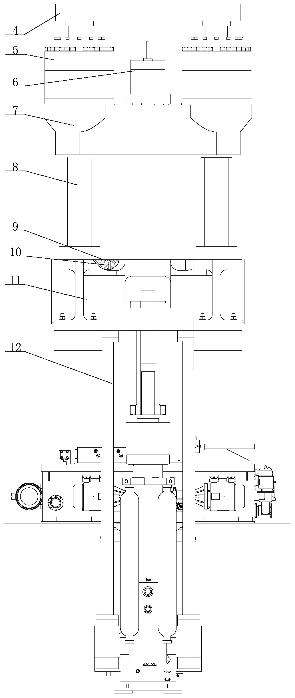
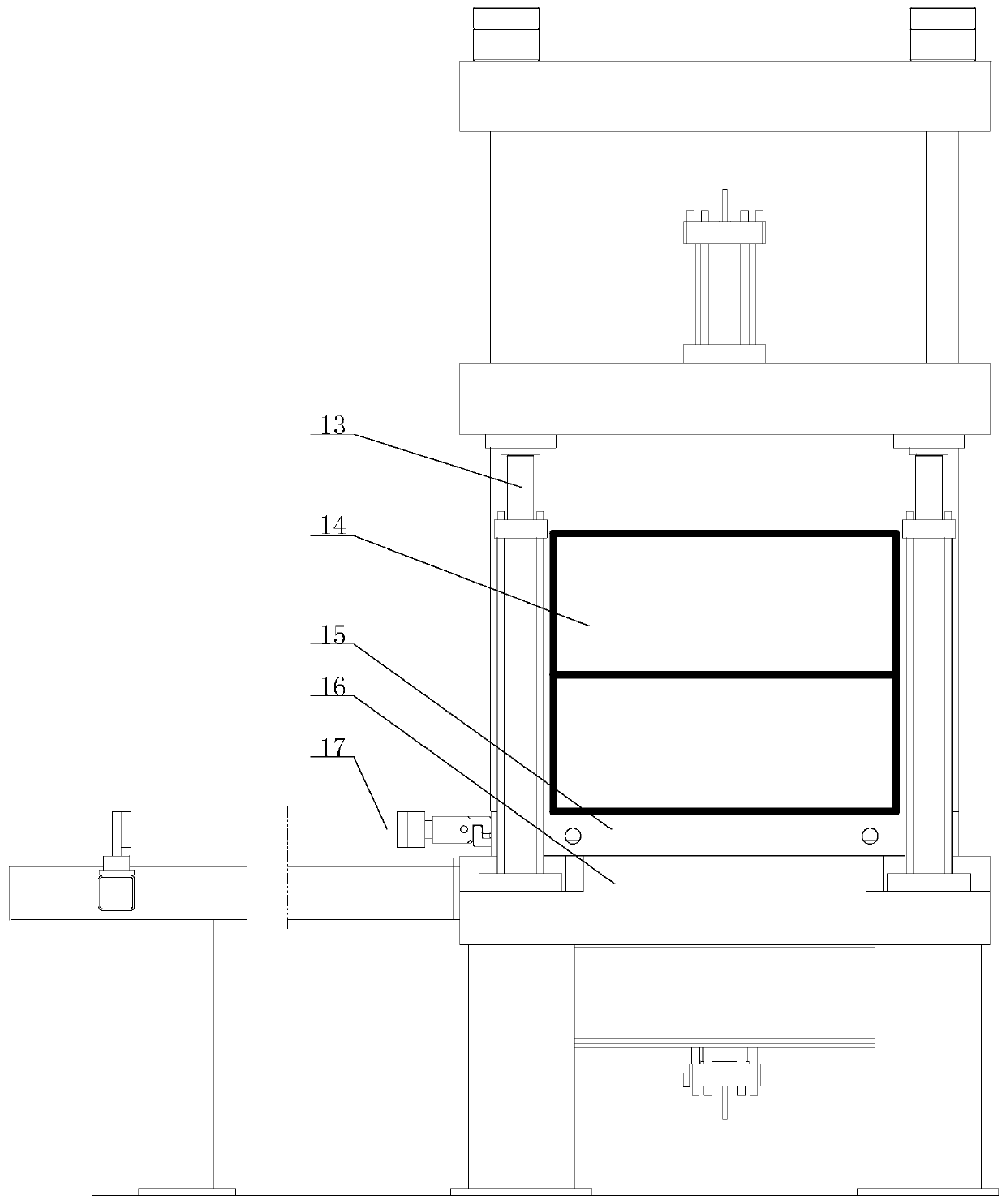
The invention relates to cooperative three-station extrusion-forging forming equipment which comprises an extrusion-forging station unit as well as mold opening and workpiece picking units, wherein the mold opening and workpiece picking units are symmetrically arranged on two sides of the extrusion-forging station unit; the bottoms of tiebars of the extrusion-forging station unit are fixed on a head plate and penetrate through a middle plate; mold locking cylinder assemblies are mounted at four corners of the middle plate; a forging cylinder assembly is mounted at the central position of the middle plate; settlement tables I are arranged on middle guide rails on the head plate; lifting oil cylinders I are in drive connection with the settlement tables I; an extrusion system is arranged below the head plate; mold opening mechanisms are mounted on working platforms of the mold opening and workpiece picking units; lateral guiding rails are laid on the working platforms; settlement tablesII are arranged on the lateral guide rails; lifting oil cylinders II are in drive connection with the settlement tables II, and used for placing mold trolleys of molds on the lateral guide rails; andlinear driving units are in drive connection with the mold trolleys, and used for driving the mold trolleys to perform reciprocating motion on the lateral guide rails and the middle guide rails. Through the left and right linear driving units, the molds can move back and forth between one extrusion-forging station as well as two mold opening and workpiece picking stations, thereby achieving the cooperation between the extrusion-forging station as well as the mold opening and workpiece picking stations.

Description

technical field [0001] The invention relates to a three-station extruding and forging forming equipment working together, which can realize the cooperative work of one extruding and forging station and two die-opening and part-taking stations. Background technique [0002] At present, squeeze casting equipment has become an urgent and necessary major equipment for the development of basic industries such as automobiles and military industries in my country. With the continuous improvement of my country's industrial level, higher and higher requirements are put forward for complete sets of squeeze casting equipment. The traditional single-station squeeze casting machine concentrates all the forming processes in one piece of equipment. The injection system is located below the mold. When the mold is cleaned and sprayed, the debris and sewage above will enter the injection system, causing mechanical and electrical failures . The mold clamping system has a large stroke when ope...

Claims


Application Information

Patent Timeline
Patent Type & Authority Applications(China)
IPC IPC(8): B21J9/00B21J5/00B21J13/14
CPCB21J5/002B21J9/00B21J13/14
Inventor 赵峰万水平李发密林其张金贾祥磊
Owner SUZHOU SANJI FOUNDRY EQUIP
Why Eureka
Try Eureka