Hole forming drill bit with lubricating oil guide-in hole

A technology of introducing hole and lubricating oil, which is applied in the direction of drilling/drilling equipment, drill repairing, twist drill, etc. It can solve the problems of inconvenient adding lubricating oil, reducing drilling wear, low efficiency, etc., and achieves compact structure, The drilling process is stable and the effect of avoiding damage

Inactive Publication Date: 2019-12-13
常州市阿凡达工具制造有限公司
View PDF0 Cites 2 Cited by
  • Summary
  • Abstract
  • Description
  • Claims
  • Application Information

AI Technical Summary

Problems solved by technology

[0002] The hole-forming drill bit is a tool that drills the round hole of the workpiece through its rotating cutting relative to the fixed axis. The hole-forming drill bit needs to be coated with lubricating oil on its outer surface during use to reduce the amount of wear during drilling. It is also necessary to apply lubricating oil to prevent corrosion, and it also needs to be placed in a special tool box to avoid collisions. Generally, it is more convenient for these hole-forming drills to be coated with lubricating oil and put in the tool box when not in use. , but it is very inconvenient to add lubricating oil during use. It is very inconvenient and inefficient to stop the drilling floor first, then remove the drilling bit and add lubricating oil to achieve the purpose.

Method used


Image

  • Hole forming drill bit with lubricating oil guide-in hole
  • Hole forming drill bit with lubricating oil guide-in hole
  • Hole forming drill bit with lubricating oil guide-in hole

Examples


Embodiment Construction

[0016] The following will clearly and completely describe the technical solutions in the embodiments of the present invention with reference to the accompanying drawings in the embodiments of the present invention. Obviously, the described embodiments are only some, not all, embodiments of the present invention. Based on the embodiments of the present invention, all other embodiments obtained by persons of ordinary skill in the art without making creative efforts belong to the protection scope of the present invention.

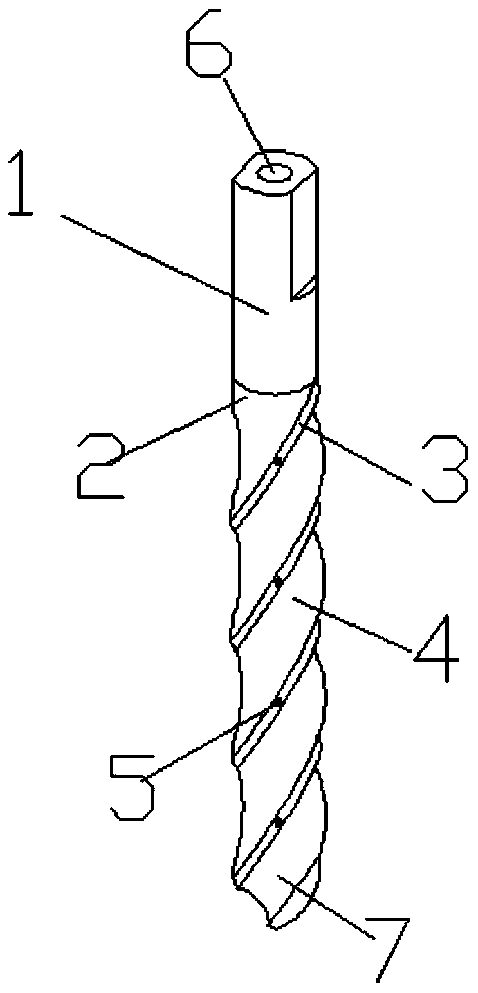
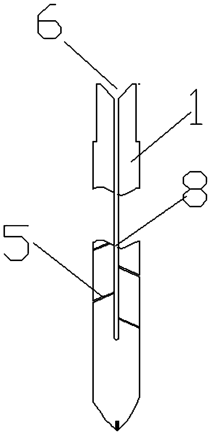
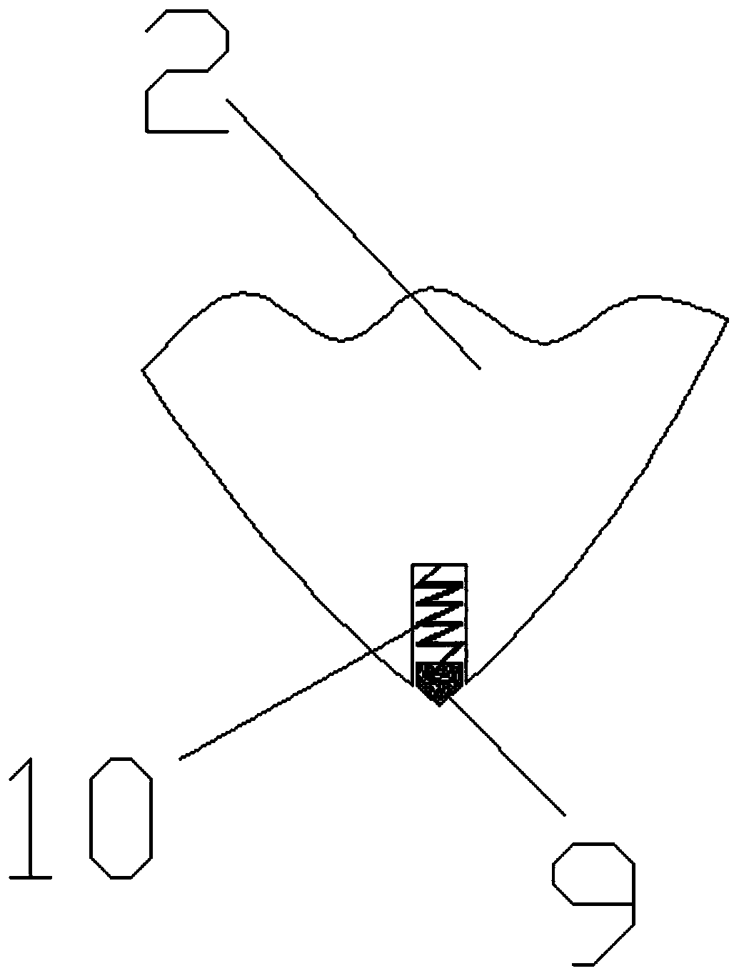
[0017] see Figure 1-4 , a hole-forming drill with a lubricating oil introduction hole, comprising a drill shank 1, a drill body 2, a cutting edge 3, a chip guide 4, an oil discharge port 5, an oil storage tank 6, a drill bit 7, an oil delivery pipe 8, and a positioning head 9 and spring 10; the lower end of the drill shank 1 is fixed with a drill body 2, each of the two sides of the drill shank 1 has a mutually symmetrical cutting plane, the lower end of the ...


PUM


Abstract

The invention discloses a hole forming drill bit with a lubricating oil guide-in hole. A drill handle, a drill body, a cutting edge, a scrap guiding groove, oil discharging ports, an oil storing groove, a drill bit body, an oil conveying pipe, a positioning head and a spring are included. The hole forming drill bit with the lubricating oil guide-in hole has the beneficial effects that the oil discharging ports which are inclined downwards in multiple directions are uniformly formed in the cutting edge, so that lubricating grease can more easily flow to the portion of the cutting edge during gradual rising of the temperature of the drill bit body; the oil storing groove is in the shape of an inverted cone, so that the lubricating grease can flow into the oil conveying pipe very convenientlyand fast under the gravity effect; the positioning head is driven by the spring to freely stretch out and draw back, a hole needing to be punched can be positioned more conveniently, and it can alsobe avoided that the positioning head is damaged; the two sides of the drill handle are each provided with a cutting plane, and the cutting planes are symmetrical about each other; and it is preventedthat the drill handle slips on a drill table, so that a drill stem is fixed more stably.

Description

technical field [0001] The invention relates to a hole-forming drill bit, in particular to a hole-forming drill bit with lubricating oil introduction holes, and belongs to the field of mechanical processing equipment. Background technique [0002] The hole-forming drill bit is a tool that drills the round hole of the workpiece through its rotating cutting relative to the fixed axis. The hole-forming drill bit needs to be coated with lubricating oil on its outer surface during use to reduce the amount of wear during drilling. It is also necessary to apply lubricating oil to prevent corrosion, and it also needs to be placed in a special tool box to avoid collisions. Generally, it is more convenient for these hole-forming drills to be coated with lubricating oil and put in the tool box when not in use. , but it is very inconvenient to add lubricating oil in the process of use. It is necessary to stop the drilling floor first, then remove the hole-forming drill bit and then add ...

Claims


Application Information

Patent Timeline
Patent Type & Authority Applications(China)
IPC IPC(8): B23B51/02B23B51/06
CPCB23B51/02B23B51/06
Inventor 李凡
Owner 常州市阿凡达工具制造有限公司
Why Eureka
Try Eureka