A support device for foundation construction steel bar welding

A technology for supporting devices and steel bars, applied in welding equipment, auxiliary devices, auxiliary welding equipment, etc., can solve the problems of high labor intensity, inability to ensure the vertical level of steel bars, uneven spacing of steel bars, etc.

Active Publication Date: 2021-08-20
NANJING YUSHENG ROBOT CO LTD
View PDF6 Cites 0 Cited by
  • Summary
  • Abstract
  • Description
  • Claims
  • Application Information

AI Technical Summary

Problems solved by technology

[0005] In order to overcome the shortcomings of uneven spacing of steel bars, high labor intensity, and inability to ensure the vertical level of steel bars, the technical problem of the present invention is to provide a cage that can ensure uniform spacing of steel bar cages, requires less labor, and can ensure the vertical level of steel bars. Supporting device for foundation construction steel bar welding

Method used


Image

  • A support device for foundation construction steel bar welding
  • A support device for foundation construction steel bar welding
  • A support device for foundation construction steel bar welding

Examples


no. 1 approach

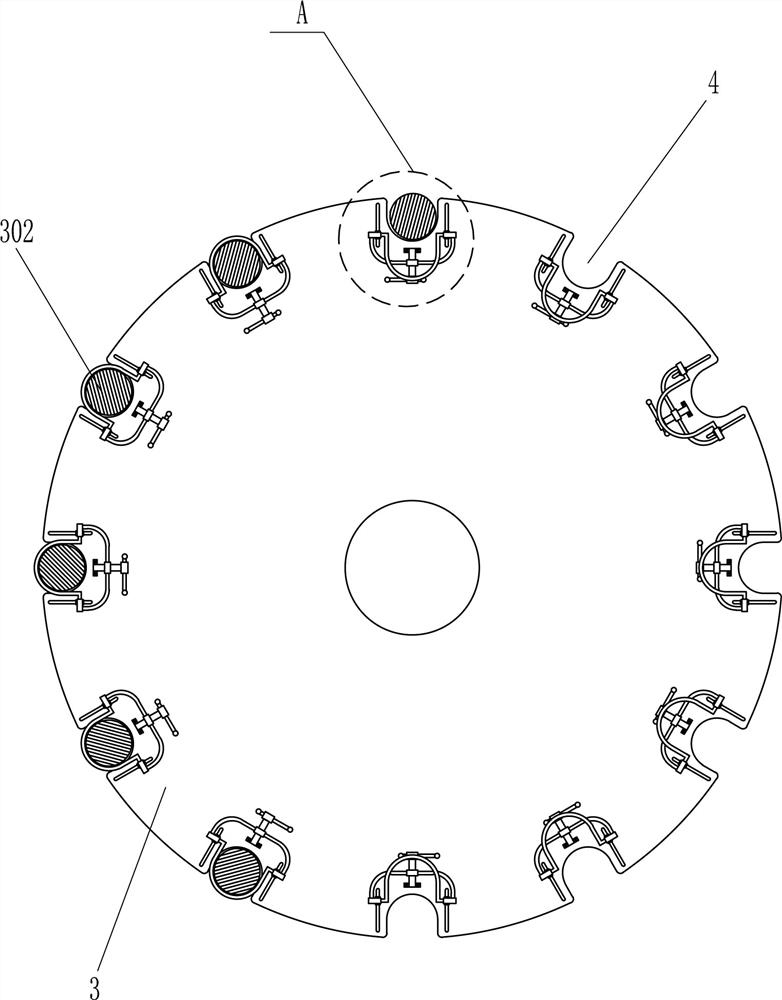
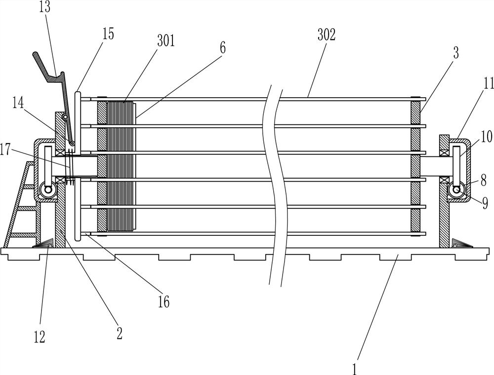
[0021] see Figure 1-Figure 3 , the application provides a supporting device for welding steel bars in foundation construction, including a base 1, a fixed plate 2 and a first disc 3, the left and right sides of the top of the base 1 are provided with fixed plates 2, and the fixed plates 2 are connected by welding The method is connected with the base 1, and the fixed plate 2 is equipped with a first disc 3 which is rotated, and the first disc 3 is provided with a connecting shaft, and the first disc 3 is rotated through the connecting shaft of the bearing seat and the fixed plate 2. Connected, the outer sides of the first disk 3 on the left and right sides are evenly provided with grooves 4 at circumferential intervals, the shape of the groove 4 is U-shaped, and a hollow tube 6 and a fixing device 5 are also included. The first disk 3 on the left The inner surface of the inner surface is provided with a hollow tube 6, and the hollow tube 6 is connected with the first disc 3 b...

no. 2 approach

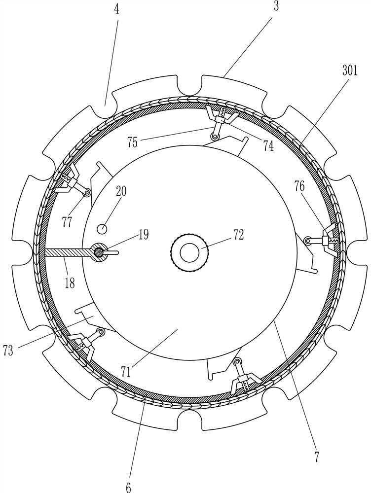
[0026] see Figure 4 , also includes a limit mechanism 7, the limit mechanism 7 includes a turntable 71, a handle 72, a wedge 73, a guide sleeve 74, a bar 75, an elastic cord and a first contact wheel 77, the first disc 3 on the left side The upper rotation type is provided with a turntable 71, the turntable 71 is connected to the first disc 3 by means of a rotating shaft connection, the turntable 71 is provided with a turning handle 72, and the turning handle 72 is welded at the center of the right side of the turntable 71, and the outer side of the turntable 71 Five wedge-shaped blocks 73 are evenly distributed, and five guide sleeves 74 are evenly distributed on the right end of the hollow tube 6. The guide sleeve 74 is slidingly provided with a retaining rod 75, and an elastic rope is connected between the retaining rod 75 and the guide sleeve 74, and the retaining rod 75 is rotatably provided with a first contact wheel 77 close to one end of the turntable 71 , and the fir...

no. 3 approach

[0029] see figure 1 and Figure 5 , also includes motor 8, worm screw 9, worm gear 10, housing 11 and foot switch 12, housing 11 is provided on the fixed plate 2 on the left and right sides, motor 8 is installed in the housing 11, on the output shaft of motor 8 A worm 9 is provided, and the worm 9 is parallel to the base 1. A worm wheel 10 is provided at the axis of the first disk 3. The worm wheel 10 is connected to the connecting shaft of the first disk 3 through an interference connection. The worm wheel 10 and The worm 9 is meshed, the worm wheel 10 and the worm 9 are all located in the housing 11, the left and right sides of the top of the base 1 are provided with foot switches 12, and the foot switches 12 are fixed on the base by means of bolt connections, and the foot switches 12 are connected to the motor. 8 are electrically connected.

[0030] When it is necessary to rotate the first disk 3 to replace the position of the groove 4, two people step on the left and rig...


PUM


Abstract

The invention relates to an auxiliary welding device, in particular to a supporting device for welding foundation building reinforcement. The technical problem of the present invention is how to design a kind of support device for foundation building steel bar welding that can ensure that the spacing of steel bar cages is uniform, the labor force is small, and the vertical and horizontal degree of steel bars can be guaranteed. The technical embodiment of the present invention is: a support device for foundation building steel bar welding includes a base, a fixed plate, a first disc, a hollow tube, etc.; A first disc is provided. The present invention clamps the strip-shaped steel bar through the fixing device to prevent the strip-shaped steel bar from falling off from the groove, so that the strip-shaped steel bar can be placed evenly, so that the shape of the steel bar foundation pile is round and standard, and can be blocked by the stop bar The steel bar ring prevents the steel bar ring from slipping, and the motor is started to make the worm wheel rotate slowly to drive the first disc to rotate. In this way, it is not necessary to manually rotate the first disc, which achieves the effect of labor saving.

Description

technical field [0001] The invention relates to an auxiliary welding device, in particular to a supporting device for welding foundation building reinforcement. Background technique [0002] The foundation pile reinforcement is a cylindrical reinforcement cage welded and fixed by the reinforcement and the reinforcement ring. This foundation pile reinforcement is generally made into a foundation pile with ordinary reinforced concrete or prestressed concrete, which saves wood and steel and is durable. , low cost and other advantages, has been widely used in hydraulic construction, industrial construction, civil construction and foundation engineering of bridges. [0003] At present, the framing and welding of the reinforcement cage are usually made by using the placenta manually. First, the reinforcement column is made, and then the reinforcement ring is used to wrap the reinforcement column inside or outside the reinforcement column, and then welded and fixed. However, this m...

Claims


Application Information

Patent Timeline
Patent Type & Authority Patents(China)
IPC IPC(8): B23K37/04
CPCB23K37/0426
Inventor 不公告发明人
Owner NANJING YUSHENG ROBOT CO LTD
Why Eureka
Try Eureka