Metal bar material blanking device and blanking method

A metal bar and cutting technology, which is applied in the direction of metal processing, metal processing equipment, metal processing machinery parts, etc., can solve the problems of poor section quality, increased production cost, low production efficiency, etc., achieve good section quality, improve efficiency, The effect of reducing loss

Pending Publication Date: 2019-12-13
XIAN AERONAUTICAL POLYTECHNIC INST
View PDF0 Cites 3 Cited by
  • Summary
  • Abstract
  • Description
  • Claims
  • Application Information

AI Technical Summary

Problems solved by technology

At present, the blanking of metal bars in industrial production usually adopts the traditional blanking method combining high-speed band saw cutting and punch shear blanking. This method has different degrees of low material utilization, low production efficiency, and high energy consumption. and poor cross-section quality
[0003] The traditional blanking methods include sawing blanking and shearing blanking. Although these two blanking methods can obtain a flat section to a certain extent, they have disadvantages such as low production efficiency and low material utilization.
For this reason, many researchers at home and abroad use shear blanking for metal bars, but the end of the blank produced by the shear blanking method has large deformation, low dimensional accuracy, serious material waste, low production efficiency, and increased production costs.

Method used


Image

  • Metal bar material blanking device and blanking method
  • Metal bar material blanking device and blanking method
  • Metal bar material blanking device and blanking method

Examples


Embodiment Construction

[0031] The present invention will be described in detail below in conjunction with the accompanying drawings and specific embodiments.

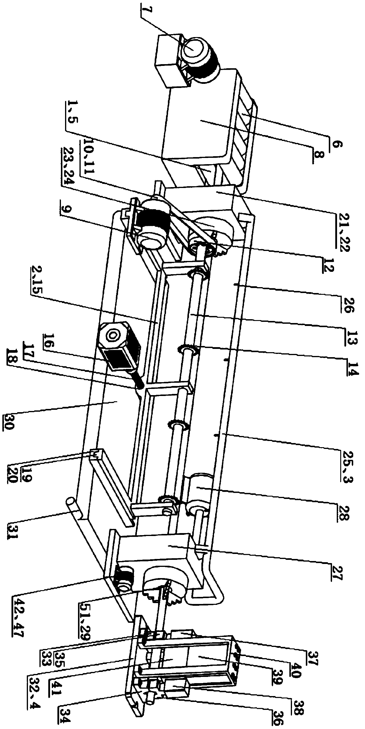
[0032] Such as figure 1 As shown, a metal bar blanking device of the present invention includes a feeding system 1; a groove milling system 2 is arranged on one side of the feeding system 1; the groove milling system 2 is connected with a clamping system 21 and a cooling system 3 respectively; the groove milling system 2 one side is provided with unloading system 4.

[0033] The feeding system 1 includes several lower idler rollers 5 arranged side by side; several upper idler rollers 6 arranged side by side are arranged above the lower idler roller 5; the upper idler rollers 6 and the lower idler rollers 5 have the same number, and the two are in one-to-one correspondence; It also includes a motor a7; the output shaft of the motor a7 is fixedly connected to one end of one of the lower idler rollers 5;

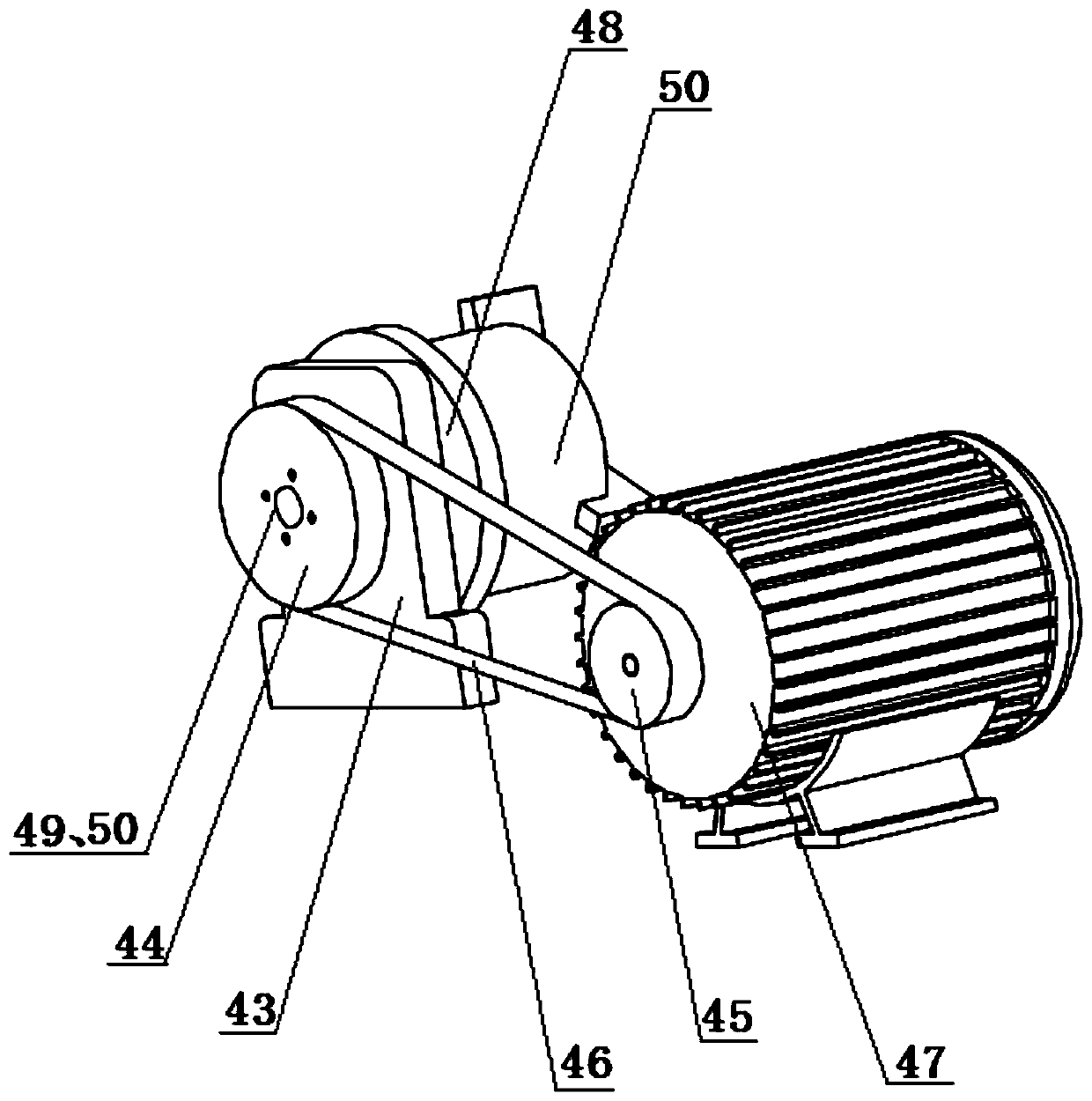
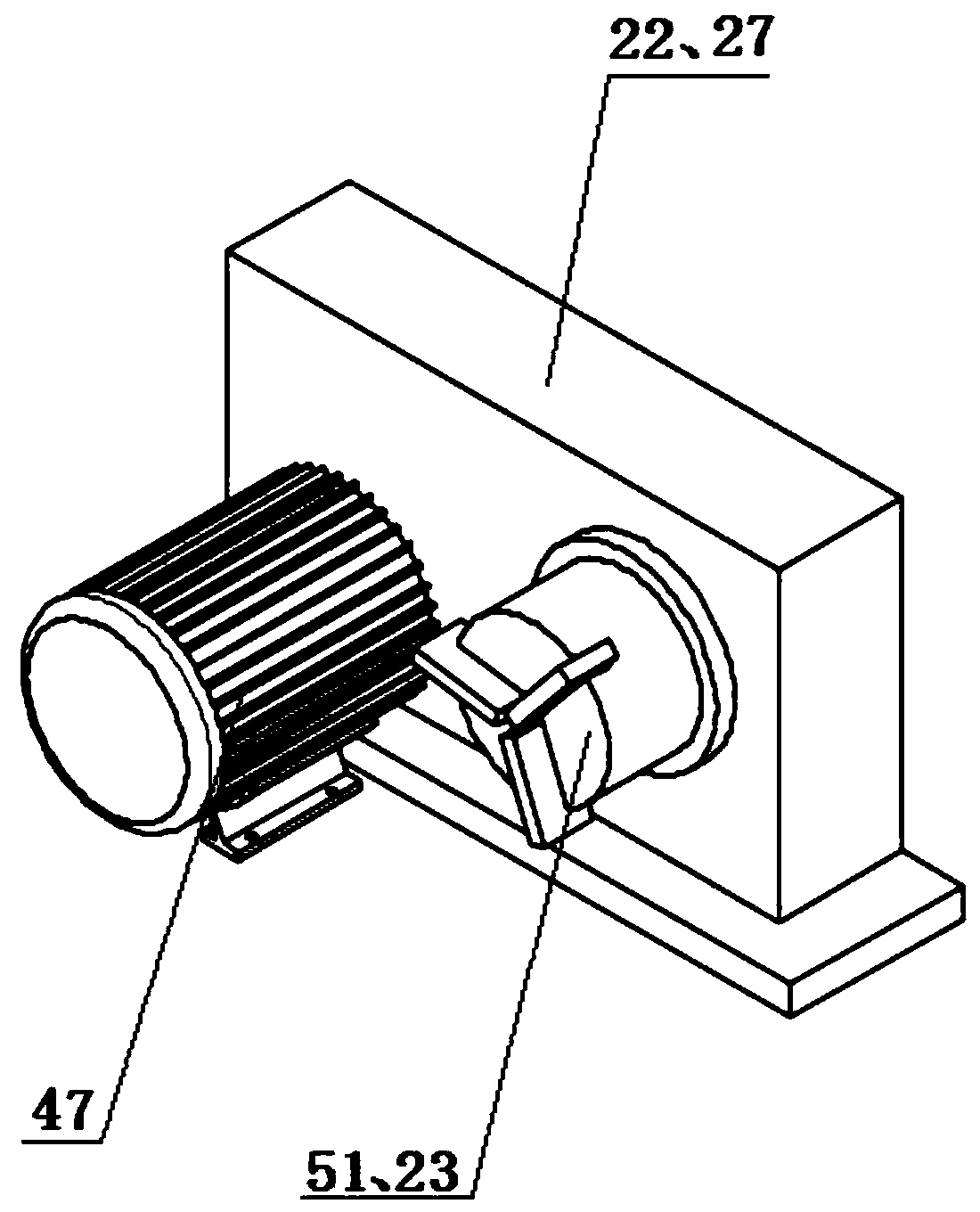
[0034] The slot milling system 2 incl...


PUM


Abstract

The invention discloses a metal bar material blanking device. The metal bar material blanking device comprises a feeding system, wherein a milling groove system is arranged on one side of the feedingsystem; the milling groove system is correspondingly connected with a clamping system and a cooling system; and a blanking system is arranged on one side of the milling groove system. The blanking method comprises the following steps of 1, feeding a metal bar material through a through hole a and a through hole b to the clamping system through the feeding system; a three-jaw chuck a and a three-jaw chuck b clamp and fix the metal bar material; 2, milling the metal bar material; 3, adjusting the position of a nozzle and the water flow speed, starting a water pump, and cooling the metal bar material; 4, loosening the three-jaw chuck a and the three-jaw chuck b, and moving the metal bar material to the blanking system through the feeding system; and 5, starting a clamping cylinder a and a clamping cylinder b to clamp and fix the metal bar material, starting an impact cylinder, and pushing a pressing block to strike the metal bar material, so that the metal bar material is disconnected.

Description

technical field [0001] The invention belongs to the technical field of bar blanking equipment, and in particular relates to a metal bar blanking device and a blanking method. Background technique [0002] Metal bars are widely used in many mechanical parts, such as various cold and hot extrusions and die forgings, metal chains, bearings and various shaft parts, etc., but almost all parts related to short shafts have bar The unloading process of the material. At present, the blanking of metal bars in industrial production usually adopts the traditional blanking method combining high-speed band saw cutting and punch shear blanking. This method has different degrees of low material utilization, low production efficiency, and high energy consumption. And problems such as poor section quality. [0003] The traditional blanking methods include sawing blanking and shearing blanking. Although these two blanking methods can obtain a flat section to a certain extent, they have disad...

Claims


Application Information

Patent Timeline
Patent Type & Authority Applications(China)
IPC IPC(8): B23P23/04B23C3/34B23Q11/10B23Q7/05B23B31/16B21D28/02B21D28/20B21D28/04
CPCB21D28/02B21D28/04B21D28/20B23B31/16B23C3/34B23P23/04B23Q7/055B23Q11/1084
Inventor 孙剑伟刘蕾李龙任小萍王博华
Owner XIAN AERONAUTICAL POLYTECHNIC INST
Why Eureka
Try Eureka