Enhanced repair method after damage of composite material blade skin

A technology of composite materials and blades, which is applied in the repair field of rotor system composite blades, can solve the problems of skin step difference, local stress concentration, easy secondary debonding, and heavy weight gain of blades, etc.

Active Publication Date: 2019-12-13
哈尔滨哈飞航空工业有限责任公司
View PDF3 Cites 5 Cited by
  • Summary
  • Abstract
  • Description
  • Claims
  • Application Information

AI Technical Summary

Problems solved by technology

[0003] During the use of composite material blades, the skin and internal foam core structure are prone to damage, which has a great impact on the structural stiffness, strength, fatigue life and flight safety of the blade
[0004] In the traditional method, the skin of the damaged area is generally repaired by injecting repair glue locally. This kind of repair method has a simple process, but there are problems such as limited repair area, local stress concentration, easy secondary debonding, and h

Method used


Image

  • Enhanced repair method after damage of composite material blade skin
  • Enhanced repair method after damage of composite material blade skin

Examples


Embodiment

[0050] In conjunction with the accompanying drawings, the implementation process of the present invention is described more comprehensively, specifically including the following steps:

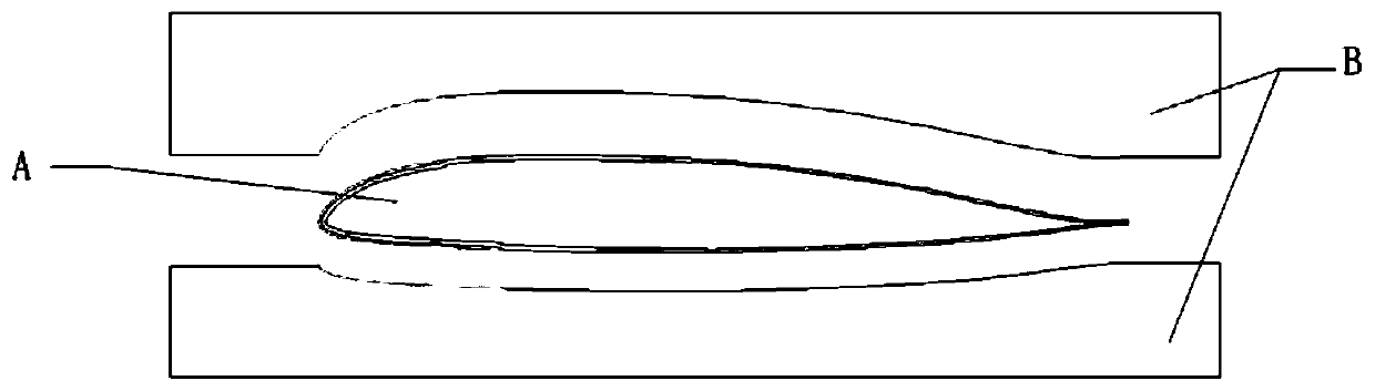
[0051] Step 1: Weigh the repaired blade A before repair, and record the weight before repair.

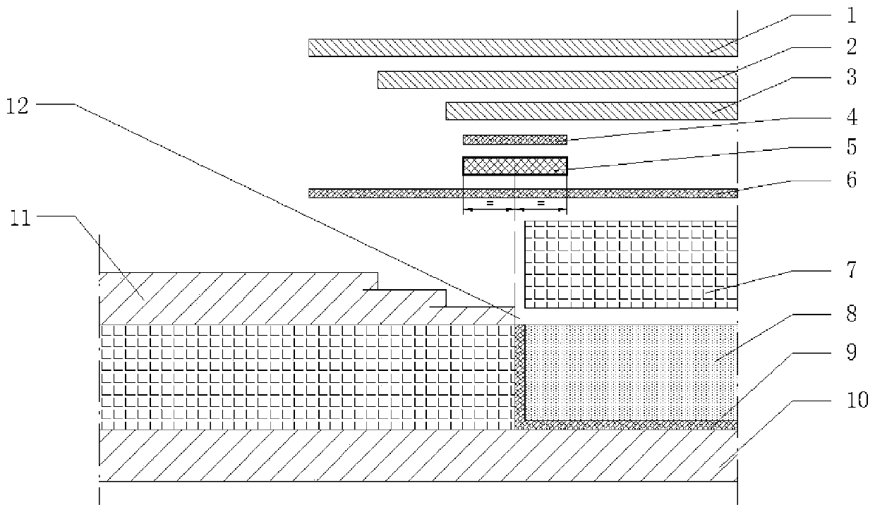
[0052] Step 2: Excavate and clean the damaged area 8 of the skin and filling core material in the repaired blade A, take the damaged area as the cleaning center, peel off the skin in this area, and clean up the area outside this area layer by layer in a stepwise manner. Each layer of skin 11 gradually increases the cleaning range from the inner skin to the outer skin, and the step width can be 15mm to 25mm. The cleaning area is generally round or rectangular, as neat as possible.

[0053] Step 3: Carry out overall grinding and cleaning of the damaged area 8 of the skin and filling core material and the area of ​​the original skin 11 peeled off by steps; place a layer of glued filling core material ...

Embodiment 2

[0064] When both the upper and lower airfoils of a composite blade to be repaired are damaged, debonded, or have penetrating scars, perform the repairs as follows:

[0065] Step 1: Carry out paint stripping treatment on the damaged area of ​​the blade skin, and weigh it before repairing.

[0066] Step 2: Clean up the damaged area of ​​the blade skin, take the damaged area as the cleaning center, peel off the upper and lower airfoil skins in this area, and clean the layers of skin outside this area layer by layer in a stepwise manner, Gradually increase the cleaning range from the inner skin to the outer skin.

[0067] Step 3: Lay a layer of film material on the cleared and filled core material area as a whole.

[0068] Step 4: Give priority to the side with the larger damage area; if the area is the same, give priority to the lower wing. Return the blade to the forming die with the side to be repaired facing up.

[0069] Step 5: Refill the core material in the cleaned area ...


PUM


Abstract

The invention belongs to repair technology of a composite material blade of a rotor system, and relates to an enhanced method after damage of a composite material blade skin and internal filling. Theenhanced method comprises the following steps that after damaged areas are cleaned, a filling area is formed; adhesive films are laid in the filling area, the bottom surface and the side surfaces of acore material filling area are coated with the adhesive films; the core material filling area is filled with core materials, adhesive film materials are laid on an entire repair area on the upper part of the filling core materials, and the all skin damaged areas are covered with the adhesive film materials; and the upper part of a docking area of the filling core materials and a blade structure is covered with a prepreg. The enhanced method is used for smoothing the small jump between the filling core materials and the blade structure.

Description

technical field [0001] The invention belongs to the composite material blade repair technology of a rotor system, and relates to an enhanced method for composite material blade skin and internal filling after damage. Background technique [0002] Composite material blades are mainly molded from structural parts such as skins, girders, foam cores, and leading edge wraps. The skin covers the entire outer surface of the blade and is an important part of the composite blade, which ensures the overall aerodynamic shape of the blade and contributes greatly to the torsional stiffness and shimmy stiffness of the blade. [0003] During the use of composite blades, the skin and internal foam core structure are prone to damage, which has a great impact on the structural stiffness, strength, fatigue life and flight safety of the blade. [0004] In the traditional method, the skin of the damaged area is generally repaired by injecting repair glue locally. This kind of repair method has ...

Claims


Application Information

Patent Timeline
IPC IPC(8): B29C73/26B29C73/30B29C73/24B29C73/04
CPCB29C73/04B29C73/24B29C73/26B29C73/30B29C2073/262B29C2073/264
Inventor 刘启迪任淼康健李丽丽颜佳瑶吕楠
Owner 哈尔滨哈飞航空工业有限责任公司
Why Eureka
Try Eureka