
Gas pressure measuring device with high safety factor and using method of gas pressure measuring device

A technology of gas pressure and safety factor, which is applied in the field of gas pressure measurement devices, can solve problems such as lack of auxiliary exhaust protection function, inconvenient installation of drilling pipe head structure, and inability to sample for inspection, so as to ensure the safety of sampling and guarantee The effect of supporting and fixing stability and ensuring accuracy

Inactive Publication Date: 2019-12-13
NORTH CHINA INST OF SCI & TECH
View PDF0 Cites 3 Cited by
  • Summary
  • Abstract
  • Description
  • Claims
  • Application Information

AI Technical Summary

Problems solved by technology

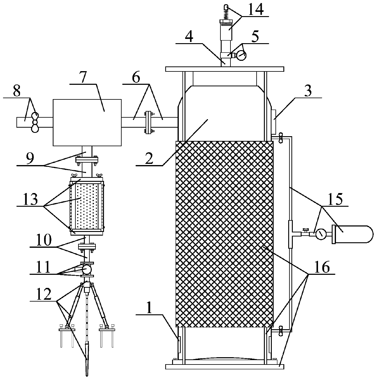
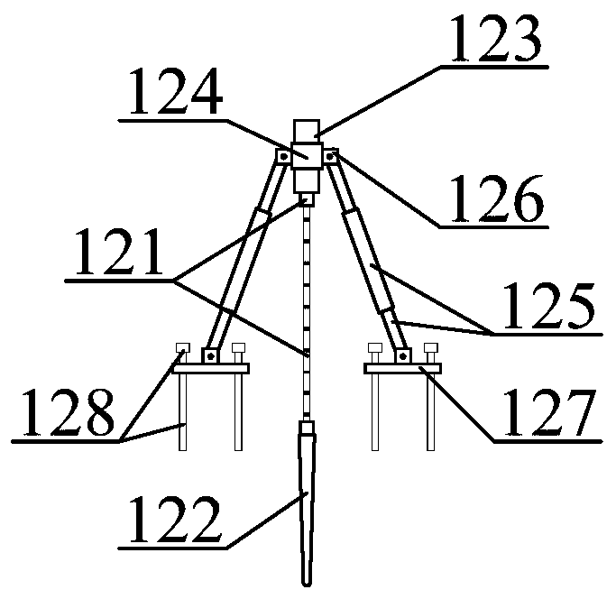
[0006] In order to solve the above-mentioned technical problems, the present invention provides a gas pressure measuring device with a high safety factor and its use method, so as to solve the problem that the existing gas pressure measuring device has impurities in the drilled gas water that affect the detection and cannot be sampled for inspection. Excessive gas-water pressure is prone to bursting hazards, does not have the auxiliary exhaust protection function and is inconvenient to install the drilling pipe head structure. A gas pressure measurement device with a high safety factor includes a gas pressure measurement sensor, a gas storage tank, Measuring data display, exhaust pipe, barometer, 1st pipe with flange connection, gas-water separator, drain pipe with valve, 2nd pipe with flange connection, 3rd pipe with flange connection, suction pump, optional Adjustable and fixed installation of the gas pipeline support frame, impurity adsorption and detachable cleaning core structure, explosion-proof auxiliary gas discharge pipe structure, removable gas sampling bottle structure and explosion-proof auxiliary protective cylinder structure, the gas pressure measurement The sensors are screw-connected to the left and right walls of the inner lower side of the gas storage tank; the upper right side of the gas storage tank is connected to the measurement data display screen with a longitudinal screw; the longitudinal lower end of the exhaust pipe is screwed to the upper part of the gas storage tank At the outlet of the middle position; the outlet of the middle position of the outer wall of the exhaust pipe is threadedly connected with a barometer; one end of the first flanged connection pipe is threaded at the upper left inlet of the gas storage tank, and the other end is threaded At the outlet of the middle position of the right end of the gas-water separator; the outlet of the middle position of the left end of the gas-water separator is threadedly connected with a drain pipe with a valve; The inlet of the middle position of the lower part of the separator; the longitudinal lower end of the third flange connection pipe is threadedly connected to the upper outlet of the suction pump; the suction pump is connected to the adjustable and fixed gas pipeline support frame; The impurity adsorption detachable cleaning core structure described above is connected between the second flanged pipe and the third flanged pipe; the explosion-proof auxiliary gas discharge pipe structure is connected to the exhaust pipe; the described The removable gas sampling bottle structure is connected to the gas storage tank; the explosion-proof auxiliary protective cylinder structure is connected to the gas storage tank; the adjustable and fixed gas pipeline support frame includes a metal flexible conduit, Conical suction pipe, outlet pipe, fixed sleeve, telescopic adjustment rod, connecting bushing, fixed feet and anchor bolts, one end of the flexible metal conduit is threaded on the upper end of the tapered suction pipe, and the other end is threaded on the outlet The lower end of the pipe; the outer wall of the outlet pipe is threadedly connected with a fixed sleeve; the telescopic adjustment rod is axially connected to the inner middle position between the connecting bushings; the connecting bushings are respectively bolted to the fixed feet The middle position of the upper part and the middle position of the left and right sides of the fixed sleeve; the inner four corners of the fixed foot are respectively longitudinally threaded with anchor bolts

Method used

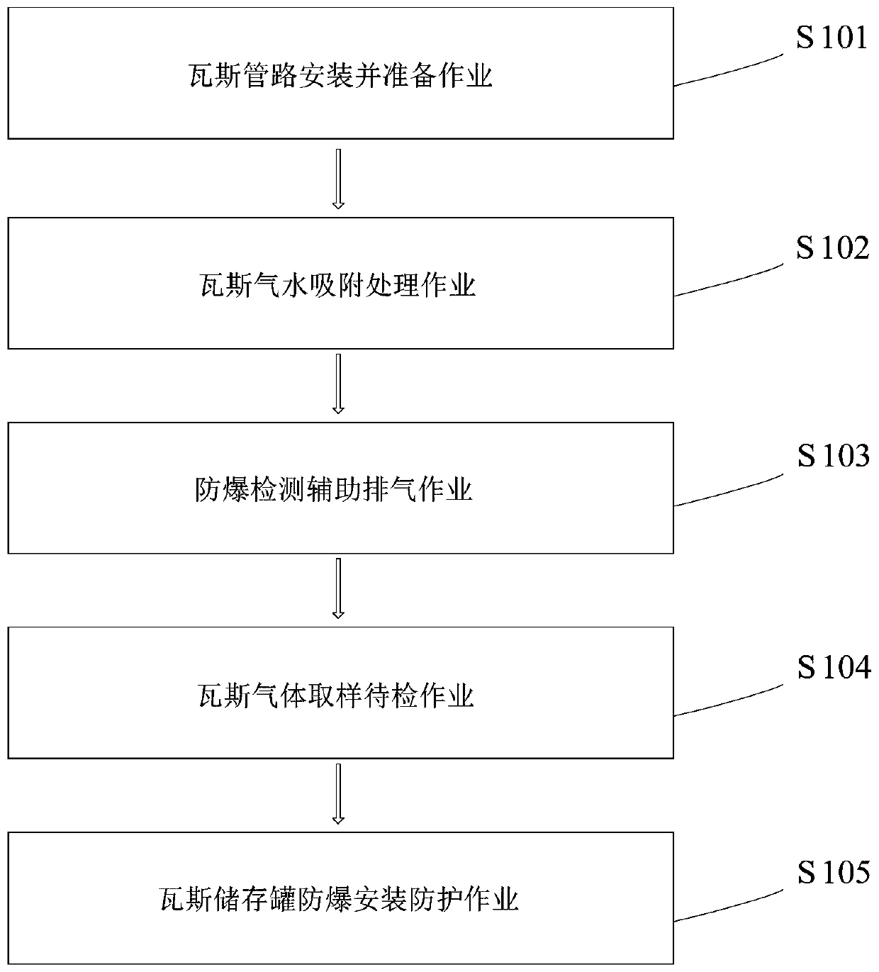

Image

  • Gas pressure measuring device with high safety factor and using method of gas pressure measuring device
  • Gas pressure measuring device with high safety factor and using method of gas pressure measuring device
  • Gas pressure measuring device with high safety factor and using method of gas pressure measuring device

Examples


Embodiment Construction

[0049] The present invention will be further described below in conjunction with accompanying drawing:

[0050] In the picture:

[0051] as attached figure 2 to attach Figure 7 shown

[0052] A gas pressure measurement device with a high safety factor, including a gas pressure measurement sensor 1, a gas storage tank 2, a measurement data display screen 3, an exhaust pipe 4, an air pressure gauge 5, a first flanged connection pipe 6, and a gas-water separation 7, drain pipe with valve 8, second pipe with flange connection 9, third pipe with flange connection 10, suction pump 11, adjustable and fixed installation of gas pipeline support frame 12, impurity adsorption and detachable cleaning core structure 13. An explosion-proof auxiliary gas discharge pipe structure 14, a removable gas sampling bottle structure 15 and an explosion-proof auxiliary protection cylinder structure 16. The gas pressure measurement sensor 1 is screwed under the inside of the gas storage tank 2 res...


PUM


Abstract

The invention provides a gas pressure measuring device with high safety factor. The gas pressure measuring device comprises a gas pressure measuring sensor, a gas storage tank, a measuring data display screen, an exhaust pipe, a gas-pressure meter, a first flanged connecting pipeline, a gas-water separator, a valved drainage pipe, a second flanged connecting pipeline, a third flanged connecting pipeline, a suction pump, an adjustable fixed installation gas pipeline supporting frame, a detachable clearing core structure capable of adsorbing impurities, an explosion-proof auxiliary gas dischargestructure, a gas sampling to-be-inspected bottle structure capable of taking and putting and an explosion-proof auxiliary protective barrel structure. According to the gas pressure measuring device,a metal soft guide pipe, a cone-shaped suction pipe and an eduction pipe are arranged, self bending is advantageously adjusted according to the bending degree of a drilled hole, gas water can be conveniently sucked out, and the smooth progress of the gas pressure measurement work is ensured.

Description

technical field [0001] The invention belongs to the technical field of measuring coal seam gas pressure, and in particular relates to a gas pressure measuring device with a high safety factor and a method for using the same. Background technique [0002] The size of coal seam gas pressure is an important index to evaluate the risk of coal seam outburst and the size of coal seam gas content. According to this index, corresponding outburst prevention measures and gas drainage methods can be taken. [0003] The current method of measuring coal seam gas pressure is mainly to directly install a pressure gauge outside the borehole of the sealed hole. When reading, someone needs to go to the scene to read the value of the pressure gauge. [0004] However, the existing gas pressure measurement device has the impurity in the drilled gas water that affects the detection, cannot be sampled for inspection, and the gas-water pressure is too high to cause the risk of bursting, does not ha...

Claims


Application Information

Patent Timeline
Patent Type & Authority Applications(China)
IPC IPC(8): E21B47/06E21B43/34E21B49/08
CPCE21B43/34E21B47/06E21B49/08
Inventor 陈鹏刘永杰陈学习谢宏杨涛
Owner NORTH CHINA INST OF SCI & TECH
Learn More