Supercharge Your Innovation With Domain-Expert AI Agents!

Compression and release type engine in-cylinder braking device

A technology of engine cylinder and braking device, which is applied in the direction of engine control, engine components, machine/engine, etc., can solve problems such as complex structure, and achieve the effects of low control circuit requirements, stable and reliable operation, and low failure rate

Pending Publication Date: 2019-12-13
WEIFANG LICHUANG ELECTRONICS TECH
View PDF1 Cites 7 Cited by
  • Summary
  • Abstract
  • Description
  • Claims
  • Application Information

AI Technical Summary

Problems solved by technology

Because the normal running state accounts for most of the running state of the entire engine, the gap compensation mechanism is in working state for most of the time when the engine is running, which puts forward higher requirements for reliability and the structure is more complicated

Method used


Image

  • Compression and release type engine in-cylinder braking device
  • Compression and release type engine in-cylinder braking device
  • Compression and release type engine in-cylinder braking device

Examples


Embodiment Construction

[0025] The present invention will be further described below in conjunction with the drawings and embodiments.

[0026] The working sequence of a six-cylinder four-stroke engine is 1-5-3-6-2-4, that is, the phase difference between the first cylinder and the sixth cylinder is 360° crank angle, and the phase difference between the second cylinder and the fifth cylinder is 360° crank angle. The third cylinder and the fourth cylinder have a phase difference of 360° crank angle. For the sake of brevity, the first cylinder is referred to as cylinder 1, the second cylinder is referred to as cylinder 2, and so on.

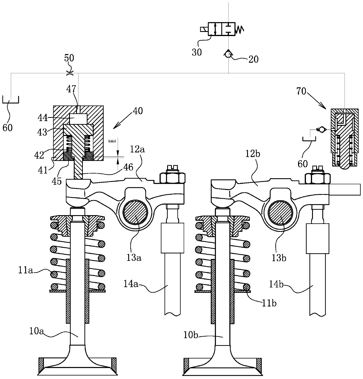
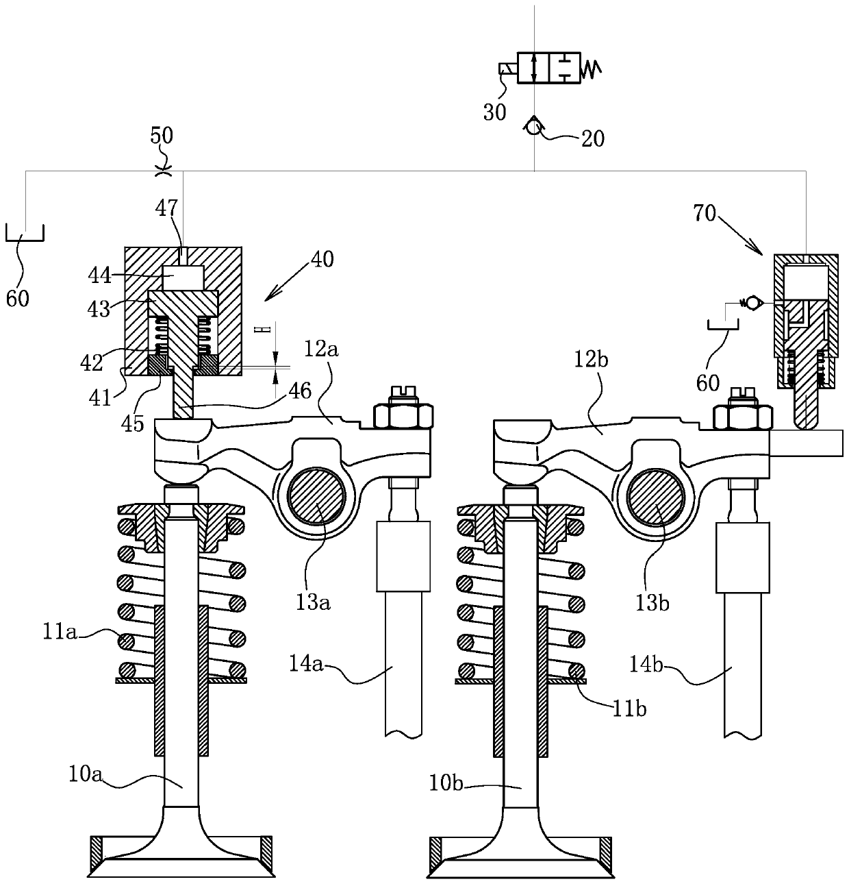
[0027] Let’s take cylinder 1 and cylinder 6 as examples. When the piston of cylinder 1 is close to the top dead center of compression, the piston of cylinder 6 is close to the top dead center of intake / exhaust. The valve begins to open and the exhaust valve closes.

[0028] Such as figure 1 with figure 2 As shown, a compression-release type engine in-cylinder brake device. Fo...


PUM


Abstract

The invention discloses a compression and release type engine in-cylinder braking device. In a pair of cylinders with the phase difference of a 360-degree crank angle, a gas discharge mechanism of thecylinder A is provided with an oil cylinder device, a gas inlet mechanism of the other cylinder B is provided with an oil pumping device, the oil pumping device is controlled by the gas inlet mechanism of the cylinder B, engine oil of an engine is pumped into the oil cylinder device, then a valve rocker of the gas discharge mechanism of the cylinder A is driven to swing, thus a gas discharge valve of the gas discharge mechanism of the cylinder A is pushed to be opened, and release braking is achieved. According to the compression and release type engine in-cylinder braking device, switching of braking and non-braking can be achieved only by controlling on-off states of a switch electromagnetic valve, the requirement for a control circuit is low, working is stable and reliable, the failurerate is low, and the compression and release type engine in-cylinder braking device is especially suitable for being used for a multi-cylinder four-stroke engine with an even number of cylinders.

Description

Technical field [0001] The invention relates to the technical field of engine in-cylinder braking, in particular to a compression-release type engine in-cylinder braking device. Background technique [0002] The engine's in-cylinder braking technology has mainly undergone the development process of exhaust butterfly valve braking, deflated braking, and compression release braking. Among them, compression release braking technology is currently the best technology for engine braking performance. The basic principle is: when the engine is dragging backwards, the piston compresses the gas in the cylinder during the upward movement of the piston in the compression stroke to generate braking power. Before the compression top dead center, the exhaust valve is driven to open a certain degree of opening through the compression release brake device, and the compressed high temperature and high pressure charge in the cylinder is discharged. At this time, the pressure in the cylinder decrea...

Claims


Application Information

Patent Timeline
Patent Type & Authority Applications(China)
IPC IPC(8): F01L13/06F01L9/02F02D13/04F01L9/12
CPCF01L13/065F02D13/04F01L9/10
Inventor 王立峰牟大为王秀强王孟晓吴龙龙王昊天从田增苏明涛衣金水吴鹏超
Owner WEIFANG LICHUANG ELECTRONICS TECH
Features
  • R&D
  • Intellectual Property
  • Life Sciences
  • Materials
  • Tech Scout
  • Unparalleled Data Quality
  • Higher Quality Content
  • 60% Fewer Hallucinations
Learn More