Device for exhaust gas aftertreatment

A technology of exhaust after-treatment and exhaust outlet, which can be used in exhaust devices, mufflers, gas channels, etc., and can solve problems such as limiting efficiency

Pending Publication Date: 2019-12-13
FORD GLOBAL TECH LLC
View PDF2 Cites 0 Cited by
  • Summary
  • Abstract
  • Description
  • Claims
  • Application Information

AI Technical Summary

Problems solved by technology

Exhaust aftertreatment systems often require a certain minimum temperature, the so-called flameout temperature, for the conversion of exhaust gases, which further limits efficiency
[0003] Furthermore, installing an internal combustion engine in the engine compartment of a motor vehicle is increasingly a challenge

Method used


Image

  • Device for exhaust gas aftertreatment
  • Device for exhaust gas aftertreatment
  • Device for exhaust gas aftertreatment

Examples


Embodiment Construction

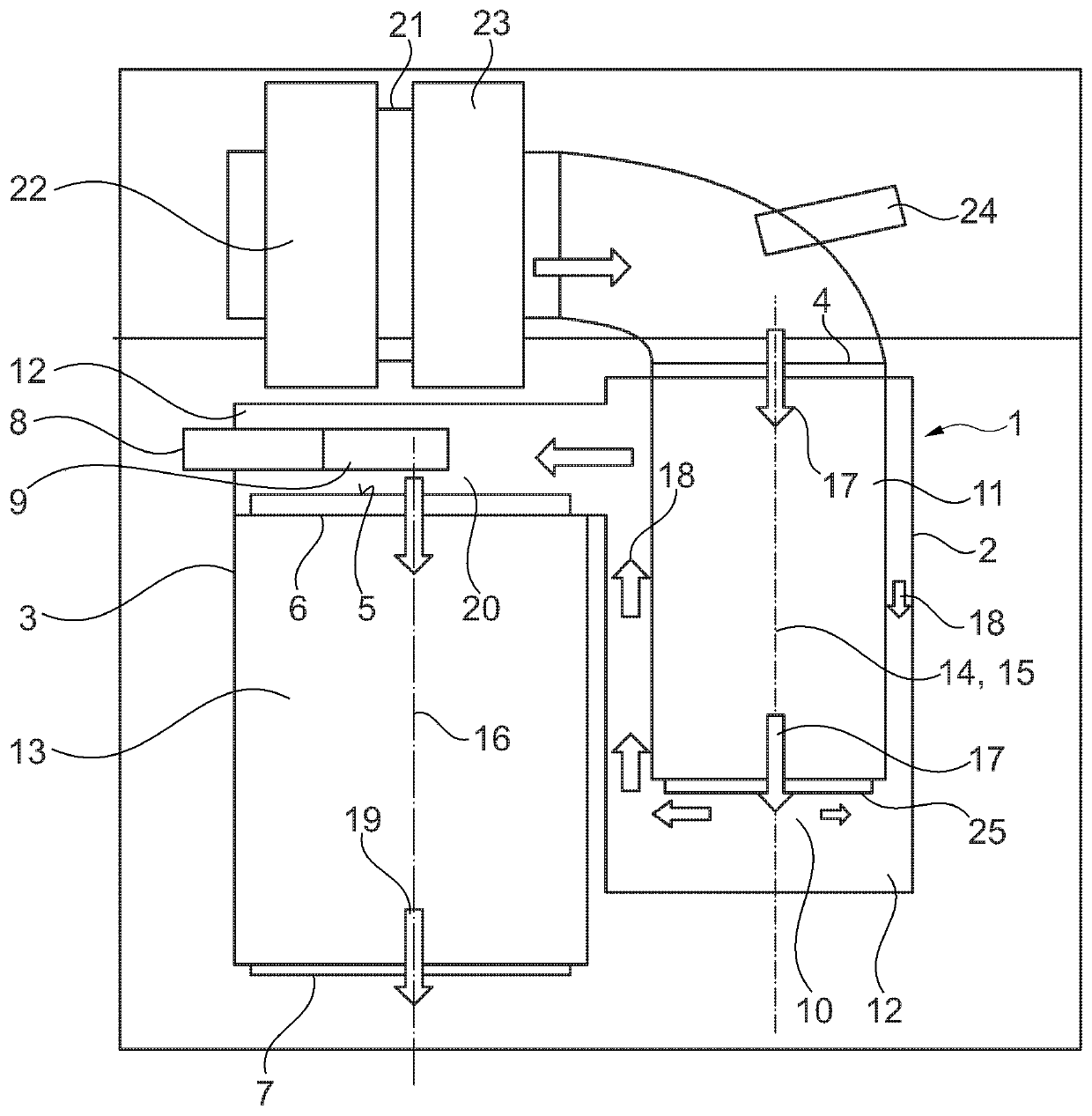
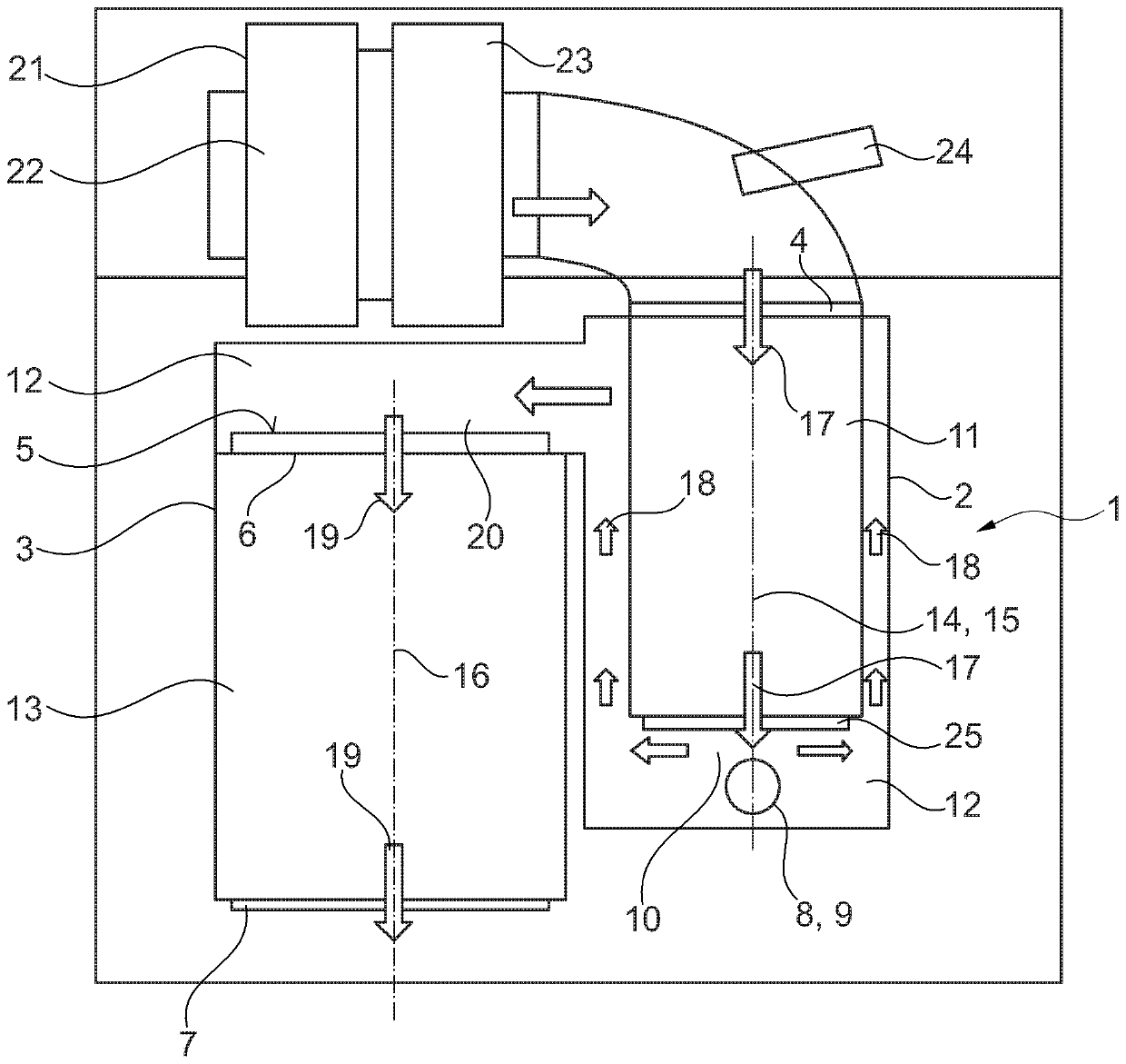
[0026] figure 1 and figure 2 Two variants of the device 1 for exhaust gas aftertreatment according to the invention are shown. The device 1 for exhaust gas aftertreatment according to the invention comprises a first catalytic converter device 2 and a second catalytic converter device 3 . The first catalytic converter device 2 comprises an exhaust gas inlet 4 and an exhaust gas outlet 5 . The second catalytic converter device 3 comprises an exhaust gas inlet 6 and an exhaust gas outlet 7, the exhaust gas inlet 6 being connected to the exhaust gas outlet 5 of the first catalytic converter device. The exhaust gas inlet 6 of the second catalytic converter device is preferably arranged vertically above the exhaust gas outlet 7 of the second catalytic converter device.

[0027] The first catalytic converter device 2 comprises a first flow channel 11 and a second flow channel 12 . The second catalytic converter device 3 comprises a third flow channel 13 . The second flow channe...


PUM


Abstract

The invention relates to a device (1) for exhaust gas aftertreatment, comprising a first catalytic converter device (2) and a second catalytic converter device (3) adjoining the first catalytic converter device (2) in the flow direction (17, 18) of the exhaust gas, the first and second catalytic converter devices being arranged spatially adjoining each other. The first catalytic converter device (2) comprises a first flow channel (11) and a second flow channel (12), and the first catalytic converter device (2) is configured to direct exhaust gas through the first flow channel (11) in a first flow direction (17) and then through the second flow channel (12) in a second flow direction (18) opposite to the first flow direction. The second catalytic converter equipment (3) comprises a third flow channel (13); the second flow channel (12) is arranged spatially and fluidically between the first flow channel (11) and the third flow channel (13), and the second catalytic converter device (3) is configured to direct the exhaust gas through the third flow channel (13) in a third flow direction (19) opposite the second flow direction after the exhaust gas has exited the second flow channel (12). The second flow channel (12) comprises means (8) for injecting a reducing agent.

Description

technical field [0001] The invention relates to a device for exhaust gas aftertreatment, a method of operating a device for exhaust gas aftertreatment, and a motor vehicle. Background technique [0002] The efficiency of the exhaust-gas aftertreatment system is basically limited, since the exhaust gas flowing into the region of the exhaust system arranged downstream of the exhaust-gas aftertreatment device still contains unused heat energy. Exhaust aftertreatment systems generally require a certain minimum temperature, the so-called flameout temperature, for the conversion of the exhaust gas, which further limits the efficiency. [0003] Furthermore, installing an internal combustion engine in the engine compartment of a motor vehicle is increasingly a challenge. The reason for this is the increasing number of additional components, each with its specific dimensions, which must be assembled with the internal combustion engine. Internal combustion engines commonly used toda...

Claims


Application Information

Patent Timeline
Patent Type & Authority Applications(China)
IPC IPC(8): F01N3/20F01N3/28
CPCF01N3/2066F01N3/28F01N3/021F01N3/0842F01N3/2892F01N13/18F01N2340/06F01N2470/08F01N2470/18Y02T10/12
Inventor B·范登赫维尔R·弗里奇B·P·卡波里
Owner FORD GLOBAL TECH LLC
Why Eureka
Try Eureka