Bearing structure of ultrathin micro pump and ultrathin micro pump

A micro-pump, ultra-thin technology, applied to parts, pumps, pump elements, etc. of pumping devices for elastic fluids, can solve problems such as low structural reliability, pre-tightened structure, small axial size, etc., to achieve Compact structure, reduced vibration and eccentricity, and high rotation accuracy

Active Publication Date: 2019-12-13
HUAWEI DEVICE CO LTD
View PDF8 Cites 1 Cited by
  • Summary
  • Abstract
  • Description
  • Claims
  • Application Information

AI Technical Summary

Problems solved by technology

However, the preload of the double bearing structure generally needs to add a mechanical fixing structure or a coil spring at both ends of the shaft to eliminate the axial play. However, the ultra-thin micropump described in this example has a small axial dimension, and there is no space at the shaft end to apply additional structure, and the bearing hole on the base of the ultra-thin micro pump is not a through hole, it is difficult to apply a traditional preload structure at both ends of the shaft
[0005] In summary, when the common bearing structures mentioned above are applied to ultra-thin micro pumps, problems such as complex structure, increased thickness, low assembly accuracy, and low structural reliability will occur.

Method used


Image

  • Bearing structure of ultrathin micro pump and ultrathin micro pump
  • Bearing structure of ultrathin micro pump and ultrathin micro pump

Examples


Embodiment Construction

[0026] In order to make the object, technical solution and advantages of the present invention clearer, the present invention will be further described in detail below in conjunction with the accompanying drawings and embodiments. It should be understood that the specific embodiments described here are only used to explain the present invention, not to limit the present invention. In addition, the technical features involved in the various embodiments of the present invention described below can be combined with each other as long as they do not constitute a conflict with each other.

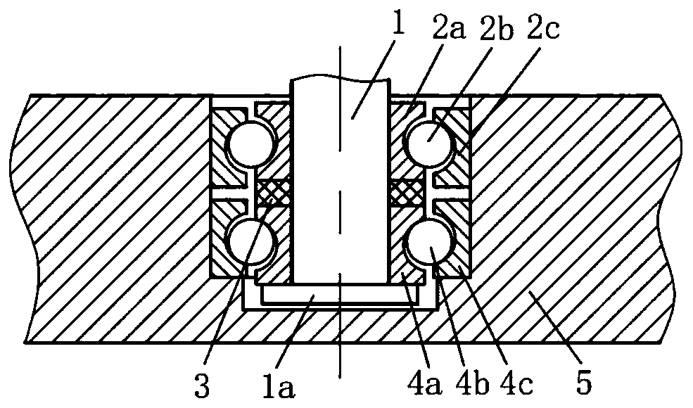
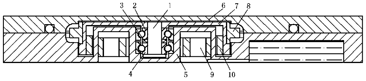
[0027] like figure 1 and figure 2As shown, it includes a blind hole, a shaft 1, a first ball bearing 4, a second ball bearing 2 and a washer 3 arranged on the ultra-thin micro pump base 5, wherein the shaft 1 is arranged at the center of the blind hole, and the The first ball bearing 4 and the second ball bearing 2 are sequentially sleeved on the shaft 1 from bottom to top, and the first ball...


PUM


Abstract

The invention belongs to the field of ultrathin rotating machinery, and particularly discloses a bearing structure of an ultrathin micro pump and the ultrathin micro pump. The bearing structure comprises a blind hole, a shaft, a first ball bearing, a second ball bearing and a gasket arranged on a base of the ultrathin micro pump; and the shaft is arranged in the center of the blind hole, the firstball bearing and the second ball bearing are sequentially arranged on the shaft from bottom to top in a sleeved mode, and the gasket is arranged between a first ball bearing inner ring and a second ball bearing inner ring or between a first ball bearing outer ring and a second ball bearing outer ring. The ultrathin micro pump comprises the bearing structure, a rotor sleeve, a volute, a base, impellers, motor magnets and motor stators. According to the bearing structure of the ultrathin micro pump and the ultrathin micro pump, the gasket is arranged to generate the stroke difference of the inner rings and the outer rings of the two ball bearings, so that balls are directly contacted with the inner rings and the outer rings of the bearings, axial clearance between the ball bearings is eliminated, positioning and pre-tightening of the double ball bearings are achieved, and the bearing structure is small in noise, long in service life and high in precision during rotation of a rotating component.

Description

technical field [0001] The invention belongs to the field of ultra-thin rotating machinery, and more specifically relates to a bearing structure of an ultra-thin micropump and the ultrathin micropump. Background technique [0002] Micropump is a power source widely used in liquid cooling systems, microfluidic systems, drug delivery and other fields to drive fluids. Requirements, and thus ultra-thin micro-pumps came into being. The ultra-thin micropump mainly includes the drive motor, the impeller that acts on the fluid, the base as the skeleton of the whole machine, and the volute that guides the fluid. The impeller is the main rotating work component, and the stable support of the impeller is related to the performance of the whole machine. Noise and reliability issues. [0003] Due to space constraints, there are many particularities in the bearing structure of ultra-thin rotating machinery. Take the existing ultra-thin micro pump as an example. (1) The size of the shaf...

Claims


Application Information

Patent Timeline
Patent Type & Authority Applications(China)
IPC IPC(8): F04D29/046F04D29/66
CPCF04D29/046F04D29/669
Inventor 罗小兵范义文吴睿康邹浩廖唯唯张信峰蓝威
Owner HUAWEI DEVICE CO LTD
Why Eureka
Try Eureka