
A method for measuring the outer circumference length and the maximum and minimum diameters of a cylindrical workpiece

A technology of maximum and minimum measurement methods, applied in the field of physics, can solve the problem of low accuracy of maximum and minimum diameters, and achieve the effect of good engineering application value, improved stability, and easy on-site implementation.

Active Publication Date: 2020-11-24
SHANGHAI RO INTELLIGENT SYST
View PDF18 Cites 0 Cited by
  • Summary
  • Abstract
  • Description
  • Claims
  • Application Information

AI Technical Summary

Problems solved by technology

[0010] Aiming at the above-mentioned technical problems in the prior art, the present invention provides a method for measuring the outer circumference and the maximum and minimum diameters of cylindrical workpieces. The method for measuring the outer circumference and maximum and minimum diameters of such cylindrical workpieces To solve the technical problem of low accuracy in measuring the outer circumference and maximum and minimum diameters of large cylindrical workpieces in the prior art

Method used


Image

  • A method for measuring the outer circumference length and the maximum and minimum diameters of a cylindrical workpiece
  • A method for measuring the outer circumference length and the maximum and minimum diameters of a cylindrical workpiece
  • A method for measuring the outer circumference length and the maximum and minimum diameters of a cylindrical workpiece

Examples


Embodiment 1

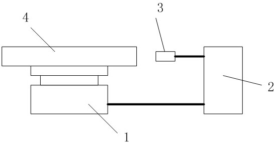
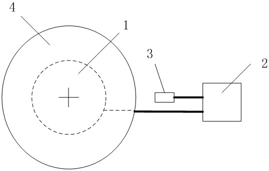
[0065] Such as figure 1 , 2 , image 3 As shown, the measuring device used in the present invention is composed of: a servo turntable 1, a control system 2, a laser displacement sensor 3, and a cylindrical workpiece 4 to be measured. The servo turntable 1 is connected to the control system 2, the laser displacement sensor 3 is connected to the control system 2, the cylindrical workpiece 4 is fixed on the servo turntable 1, and the The laser displacement sensor 3 is aligned with the cylindrical surface of the measured cylindrical workpiece 4 along the radial direction of the servo turntable 1 .

[0066] In this embodiment, the servo motor of the servo turntable 1 is specifically a Siemens 1FK7 servo motor; the control system 2 specifically uses a Siemens S7 1200PLC and S120 driver; the laser displacement sensor 3 is specifically a Panasonic HG-C1100; the cylindrical workpiece is specifically a nominal A thin-walled cylinder with a diameter of 218mm;

[0067] In this embodim...

Embodiment 2

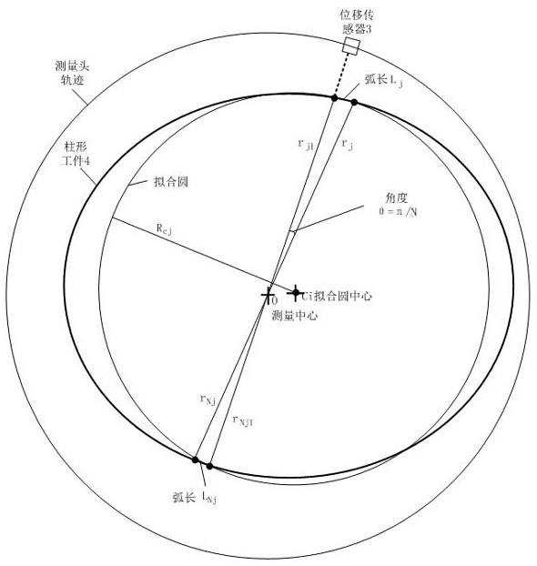
[0107] Such as Figure 4 Shown, the fitting radius formula that the present invention adopts can be described as following geometry problem:

[0108] Known: A, B, C, and D share a circle, and the center of the circle is assumed to be C j ; AC, BD intersect at O; ∠AOB=θ; AO=r j ;CO=r Nj ;BO=r j1 ;DO=r Nj1 ;

[0109] Seek: Circle C j The radius R cj

[0110] Solution: pass O, C j Circle C j The diameter EF, let |OC j |=d, easy to know So there are:

[0111]

[0112] That is:

[0113] Similarly, there are:

[0114] In the case that A, B, C, and D are not co-circular, it can be fitted by taking the average of the sum of the above two formulas to obtain:

[0115]

[0116] which is:

[0117] by C j Draw the vertical line C of AC and BD respectively j G, C j H, easy to know O, G, H, C j Co-circle, set circle Q, it is easy to know that the diameter of circle Q is d.

[0118] Construct a circle Q with diameter GI through G, so there is ∠GIH=∠GOH=θ;

...

Embodiment 3

[0132] Example 3 Calibration

[0133] Calibration work should be done before the method of the present invention is put into practical use, and the calibration work is to measure after the equipment installation is completed: the distance D between the zero position of the displacement sensor and the center of the servo shaft 0 .

[0134] Proceed as follows:

[0135] 1) Clamp a workpiece to be measured, and measure its circumference manually;

[0136] 2) Estimate a D in advance 0 estimated value;

[0137] 3) Utilize the control system to automatically measure and calculate the girth value according to the method of the present invention, the result is compared with the girth value of 1), and the subtraction obtains the girth error value;

[0138] 4) If the circumference error value is outside the allowable range, adjust D 0 Estimated value, repeat 3) until the error is smaller than the expected value.

[0139] The measurement process is divided into three steps. The firs...


PUM


Abstract

The invention relates to a method for measuring the outer circumference and maximum and minimum diameters of a cylindrical workpiece. The method comprises the following steps of: measuring device preparation; and data measuring and recording. According to the measuring device preparation step, a laser displacement sensor is adopted; and the laser displacement sensor rotates around a to-be-measuredcylindrical workpiece or the to-be-measured cylindrical workpiece rotates around the center axis of the to-be-measured cylindrical workpiece and the laser displacement sensor is stationary. Accordingto the data measuring and recording step, M measuring points are selected from the to-be-measured cylindrical workpiece; measurement is initiated; with every four points taken as a group, the measurement data of every four points are fitted into a circle according to a certain rule; the sum of the arc lengths of two diagonal short arcs is calculated, so that the diameter and arc length of the four-point group is obtained; and the arc lengths of all the four-point groups are added, so that a required perimeter can be obtained; and a maximum value and a minimum value are found out from the diameters of all the four-point groups, so that a required maximum diameter and a required minimum diameter can be obtained. With the method of the invention adopted, the precision and stability of perimeter measurement are improved; and requirements for the roundness of a workpiece and the centering degree of the installation of the workpiece are greatly lowered. The method has a high engineering application value.

Description

technical field [0001] The invention relates to the field of physics, in particular to measurement technology, in particular to a method for measuring the outer circumference and the maximum and minimum diameters of cylindrical workpieces. Background technique [0002] Cylindrical workpieces, such as the caps made in the production process of tank cars, after processing, their size consistency is not ideal, so it is necessary to manually measure the outer circumference of the edges, and then group them according to the measured values, and compare them with the cylinder one by one. Optional, finally welded with the cylinder. Since the diameter of the cover is about 3m, manual measurement is inconvenient, and the efficiency is low and error-prone. In addition to the size deviation, the cover also has a deviation in roundness, that is, a certain elliptical deformation, and it is difficult to accurately measure the maximum diameter, minimum diameter and their angular position,...

Claims


Application Information

Patent Timeline
Patent Type & Authority Patents(China)
IPC IPC(8): G01B11/02G01B11/08
CPCG01B11/026G01B11/08
Inventor 覃江华李利强
Owner SHANGHAI RO INTELLIGENT SYST
Learn More