Calibration method and calibration device of multi-shaft force sensor

A multi-axis force sensor and sensor technology, applied in the direction of force/torque/power measuring instrument calibration/testing, measuring devices, instruments, etc., can solve problems such as heavy workload, interference, installation error, etc., and reduce the adjustment workload , The device is convenient and effective, and the effect of improved accuracy

Active Publication Date: 2019-12-13
CHINA ACAD OF AEROSPACE AERODYNAMICS
View PDF14 Cites 4 Cited by
  • Summary
  • Abstract
  • Description
  • Claims
  • Application Information

AI Technical Summary

Problems solved by technology

Compared with the single-axis force sensor, the multi-axis force sensor requires much higher installation accuracy during the calibration process, especially the angular installation error around the axis, which will cause one of the load components to be loaded on the other component. Interference, which directly restricts the loading accuracy of the calibration, resulting in a decrease in the accuracy level of the multi-axis force sensor
[0004] At present, in order to suppress the above-mentioned installation errors at home and abroad, it is more common to establish a calibration coordinate system for each calibration, and adjust all the loading devices to be consistent with the coordinate system. This method has a huge workload and low efficiency. Inconsistent coordinate systems, often poor sensor alignment
At present, no high-precision and fast installation method has been seen, which has become a technical bottleneck restricting the batch precision calibration of multi-axis force sensors

Method used


Image

  • Calibration method and calibration device of multi-shaft force sensor
  • Calibration method and calibration device of multi-shaft force sensor
  • Calibration method and calibration device of multi-shaft force sensor

Examples


Embodiment Construction

[0051] The present invention mainly aims at the problem of insufficient installation and positioning accuracy in the current multi-axis force sensor calibration process, and provides an installation method for adjusting the attitude, which can keep the installation states of different sensors consistent, thereby eliminating the problems caused by differences in the installation states of the sensors. Error, improve the calibration accuracy of the sensor. The specific implementation manners of the present invention will be further described in detail below in conjunction with the accompanying drawings.

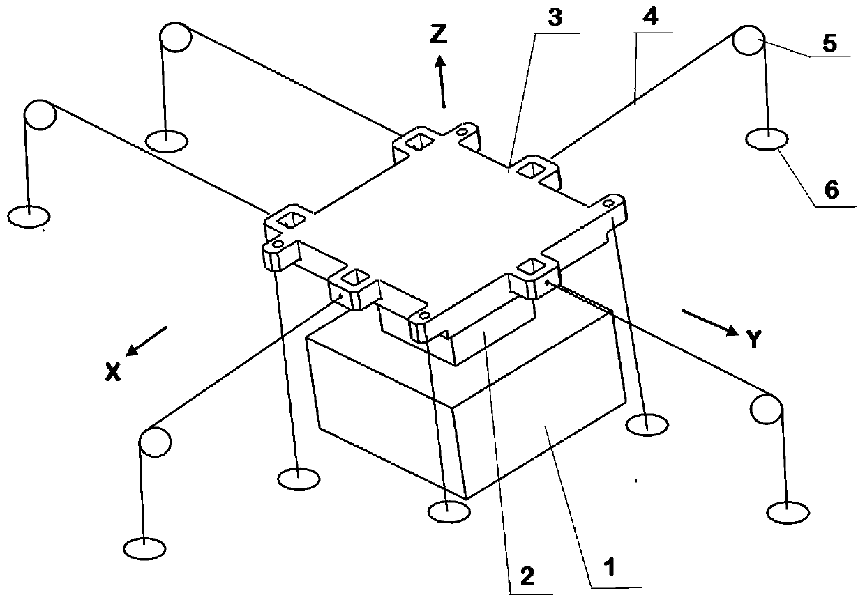
[0052] An installation and positioning method used in the calibration process of a multi-axis force sensor, the schematic diagram of the multi-axis force sensor installed on the calibration table is shown in the attached figure 1 As shown, the main components include a support mechanism 1, a multi-axis force sensor 2, a loading plate 3, a steel wire 4 connecting the loading pla...


PUM


Abstract

The invention relates to a calibration method and calibration device of a multi-shaft force sensor. Decomposition of a force and torque is achieved by a loading plate, high-accuracy synergic loading of six component loads of the multi-shaft force sensor is finally achieved, and the calibration accuracy of the sensor is improved. All position gestures of the multi-shaft force sensor can be obtainedonly by seven laser displacement sensors, and the device is convenient and effective. A newly-installed multi-shaft force sensor can be rapidly adjusted to a designated reference each time when a newsensor is arranged, all installation positions of all arranged sensors can be enabled to be consistent, the calibration reference consistency is ensured, and the consistency of different batches of sensors is greatly improved. After the sensor is installed by employing the calibration method and the calibration device, the deformation of the sensor under effects of different loads can be monitored in real time during the calibration process, and the deformation is used as a technical parameter of the sensor and is provided for a user; and compared with a traditional means for estimation by afinite element theory, the parameter acquisition method has the advantages of more trueness and more accuracy.

Description

technical field [0001] The invention relates to a multi-axis force sensor calibration method and a calibration device, which are used to avoid calibration errors caused by different batches of sensors due to different installation states, and belong to the application field of force sensors. Background technique [0002] According to different application occasions, the structural forms of multi-axis force sensors vary greatly. For example, the wind tunnel balances used in wind tunnel tests are generally rod-type structures, and the general hub-type structures used in the field of industrial robots are mostly. However, no matter what kind of field the multi-axis force sensor is used in, it needs to be calibrated before it is manufactured and put into practical use, so as to obtain the corresponding relationship between the three force components and three torque components and the output signal. [0003] The core step of the calibration of the force sensor is to install the ...

Claims


Application Information

Patent Timeline
Patent Type & Authority Applications(China)
IPC IPC(8): G01L25/00G01L5/16
CPCG01L5/16G01L25/00
Inventor 刘春风刘训华文帅刘家骅王金印
Owner CHINA ACAD OF AEROSPACE AERODYNAMICS
Why Eureka
Try Eureka