Boundary nesting method and system based on remote sensing interpretation, storage medium and equipment

An interpretation and remote sensing technology, applied in the field of boundary fitting based on remote sensing interpretation, can solve problems such as narrow and long boundaries, low processing efficiency, and fragmentation, and achieve the effect of saving labor costs and improving efficiency

Active Publication Date: 2019-12-13
SUZHOU ZHONGKE IMAGE SKY REMOTE SENSING TECH CO LTD
View PDF4 Cites 0 Cited by
  • Summary
  • Abstract
  • Description
  • Claims
  • Application Information

AI Technical Summary

Benefits of technology

This patented technology allows for efficient border matching by create elements from remotely-sensed images without human interference or effort. It then combines these elements together to generate lines that are lined up correctly along their borders. These processes can be done autonomously instead of requiring humans' input during this process.

Problems solved by technology

This patented technical solution describes two issues: 1) It cannot tell if an automated border or a hand-drawn street map have already been created correctly during autonomous driving testing due to errors introduced into them through human input; 2) There may also exist differences where different types of roads can lead to similar results even though their borders were previously painted differently on both maps (known as ghost edges). These variations make it difficult to determine which part of these areas needs modification beforehand because existing methods require significant effort from experts overseeing each area separately.

Method used


Image

  • Boundary nesting method and system based on remote sensing interpretation, storage medium and equipment
  • Boundary nesting method and system based on remote sensing interpretation, storage medium and equipment
  • Boundary nesting method and system based on remote sensing interpretation, storage medium and equipment

Examples


Embodiment Construction

[0079] Below, the present invention will be further described in conjunction with the accompanying drawings and specific implementation methods. It should be noted that, under the premise of not conflicting, the various embodiments described below or the technical features can be combined arbitrarily to form new embodiments. .

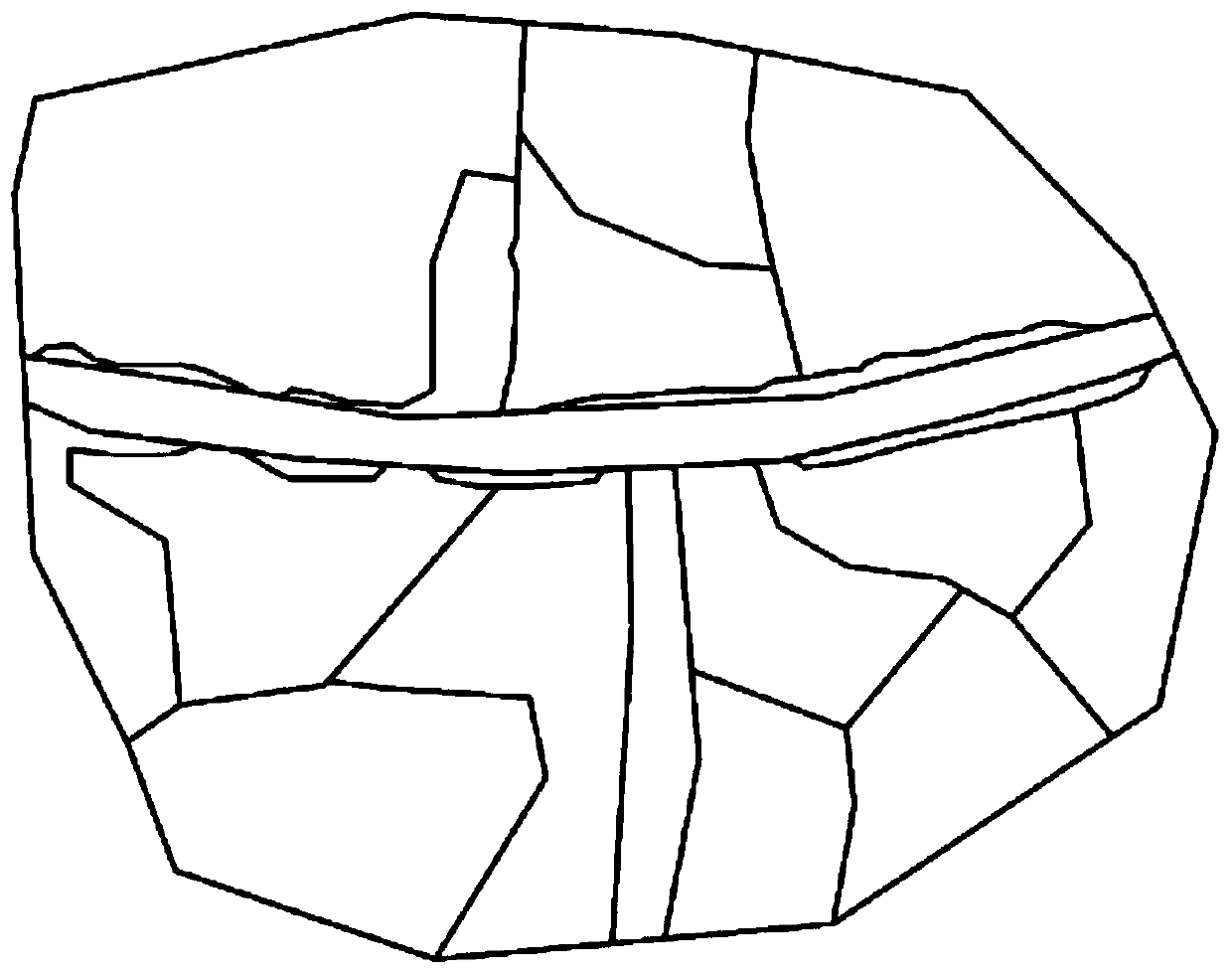
[0080] It should be noted that the boundary fitting method based on remote sensing interpretation of the present invention is aimed at long strips that form a network, such as roads and rivers.

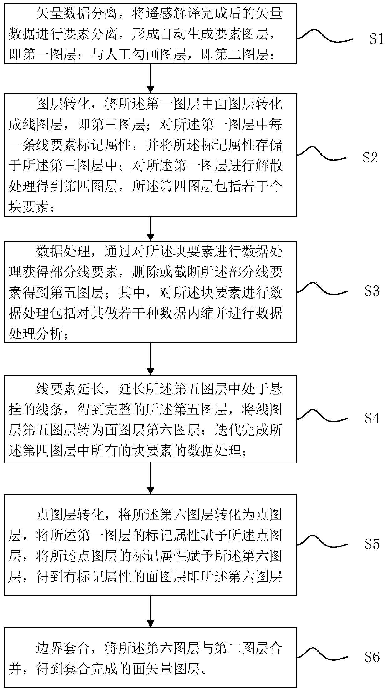
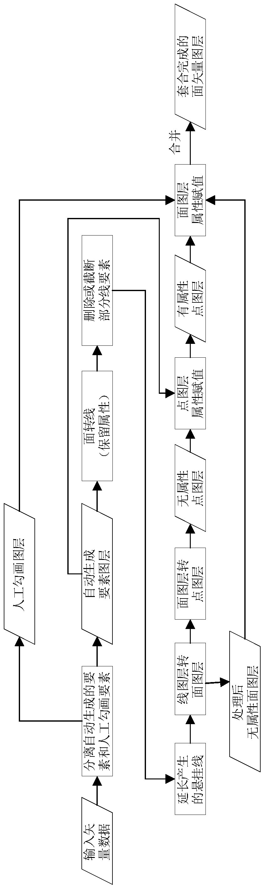
[0081] Boundary fit method based on remote sensing interpretation, such as Figure 1-2 shown, including the following steps:

[0082] S1. Separation of vector data, separating the elements of the vector data after remote sensing interpretation to form an automatically generated feature layer, that is, the first layer; and a manual sketching layer, that is, the second layer; in one embodiment, After the remote sensing interpretation of the remote sensing imag...


PUM


Abstract

The invention provides a boundary nesting method based on remote sensing interpretation. The boundary nesting method comprises the following steps of vector data separation, layer conversion, data processing, line element extension, point layer conversion and boundary nesting. The invention further relates to a boundary nesting system based on remote sensing interpretation, a storage medium and electronic equipment. According to the method, element separation is carried out on vector data after remote sensing interpretation to form an automatically generated element layer and an artificially sketched layer; according to the method, the automatically generated element graph layer is converted into the line graph layer, the graph layer obtained after data processing is conducted on the linegraph layer is combined with the manually sketched graph layer, the surface vector graph layer obtained after nesting is completed is obtained, full-automatic processing is achieved, the boundary nesting efficiency is improved, and the labor cost is saved.

Description


Claims


Application Information

Patent Timeline
Owner SUZHOU ZHONGKE IMAGE SKY REMOTE SENSING TECH CO LTD
Why Eureka
Try Eureka