Method for generating frequency modulation signal based on light injection locking

A technology of frequency modulation signal and injection locking, applied in the direction of electromagnetic wave transmission system, electromagnetic transmitter, electrical components, etc., can solve the problems of poor stability, discontinuous phase, non-tunable, etc., and achieve the effect of solving poor stability

Active Publication Date: 2019-12-13
TIANJIN UNIV
View PDF3 Cites 9 Cited by
  • Summary
  • Abstract
  • Description
  • Claims
  • Application Information

AI Technical Summary

Problems solved by technology

[0007] Aiming at the prior art, the present invention provides a method for generating a frequency modulation signal based on optical injection locking, which solves the problems of poor stability, phase discontinuity, and non-tunability of the existing injection locking technology, and the system structure of the present invention is simple and easy to implement , can be used as a stable signal generator to generate broadband tunable linear frequency modulation signals

Method used


Image

  • Method for generating frequency modulation signal based on light injection locking
  • Method for generating frequency modulation signal based on light injection locking
  • Method for generating frequency modulation signal based on light injection locking

Examples


Embodiment Construction

[0025] The present invention will be further described below in conjunction with the accompanying drawings and specific embodiments, but the following embodiments in no way limit the present invention.

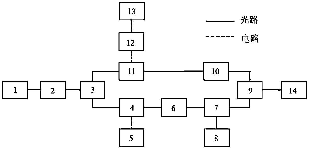
[0026] A method for generating a frequency modulation signal based on optical injection locking proposed by the present invention, such as figure 1 As shown, the electronic devices and optical devices involved include: a first laser 1, a second laser 8, a first microwave source 13, a second microwave source 5, a microwave amplifier 12, a first coupler 3, a second coupler 9, a first polarization controller 6, a second polarization controller 10, an isolator 2, an intensity modulator 4, a circulator 7, an acousto-optic frequency shifter 11 and a photodetector 14.

[0027] Both the first laser 1 and the second laser 8 are lasers without an isolator, and the first laser 1 , the isolator 2 , and the first coupler 3 are all polarization-maintaining optical devices.

[0028] The inv...


PUM


Abstract

The invention discloses a method for generating a frequency modulation signal based on light injection locking. A first laser, a second laser, a first microwave source, a second microwave source, a microwave amplifier, a first coupler, a second coupler, a first polarization controller, a second polarization controller, an isolator, an intensity modulator, a circulator, an acousto-optic frequency shifter and a photoelectric detector are included. The temperature and current parameters of a first laser are adjusted to modulate the first laser, wherein one path modulates an optical signal into asideband through an intensity modulator, and then injects and locks the modulated sideband of the optical signal into a second laser without an isolator, so that the phase of the second laser is locked to a high-order sideband of the first laser; the other path outputs a signal of which the frequency can be linearly changed through an acousto-optic frequency shifter; and then, the two paths of light are coupled by the second coupler, the output end of the second coupler and the photoelectric detector beat frequency to generate a frequency modulation signal with tunable high-frequency broadband, and the frequency modulation signal has the advantages of continuous phase and high stability.

Description

technical field [0001] The invention relates to a system for generating frequency modulation signals based on optical injection locking Background technique [0002] The Linear Frequency Modulation (LFM) signal is a pulse compression signal commonly used in radar systems. It can increase the radio frequency pulse width, increase the average transmission power, and increase the communication distance while maintaining sufficient signal spectrum width to ensure the radar. Resolution, so it has been widely used in the field of radar and sonar detection. Pulse compression radar sends LFM signal with wider pulse width when working, and performs pulse compression on it when receiving, so as to extract the distance information of the target; therefore, how to generate high-quality LFM signal is very important for pulse compression radar. With the development of radar, more and more researchers began to seek the method of generating LFM signal with low complexity and high spectral ...

Claims


Application Information

Patent Timeline
Patent Type & Authority Applications(China)
IPC IPC(8): H04B10/50H04B10/54H04B10/548H04B10/572
CPCH04B10/503H04B10/54H04B10/548H04B10/572
Inventor 于晋龙刘莉王菊马闯
Owner TIANJIN UNIV
Why Eureka
Try Eureka