
Molecular motion inhibition device for agricultural chemical packaging

A technology of molecular motion and suppression device, which is applied in the field of pesticide packaging, can solve the problems of affecting the air environment, insufficient packaging quantity, poisoning, etc., and achieve the effect of reducing the flow area and flow speed

Inactive Publication Date: 2021-03-30
HUNAN UNIV OF TECH
View PDF0 Cites 0 Cited by
  • Summary
  • Abstract
  • Description
  • Claims
  • Application Information

AI Technical Summary

Problems solved by technology

[0003] With the development of science and technology, the packaging technology of pesticides has been automated. When packaging powdered pesticides, at the position of the filling mouth, due to the relatively large force of the powder flowing out, it will be subject to greater force when it comes into contact with the packaging bag. Impact force, this impact force will break up the powder, the powder will form micromolecules, and flow out from the filling port. Macroscopically, there will be a large amount of pesticide powder splashed and scattered into the surrounding air, affecting the air environment, and due to these Pesticides are toxic, and being absorbed by the human body will cause poisoning; in addition, the splashed pesticides will also lead to insufficient packaging. Therefore, a molecular motion suppression device for pesticide packaging came into being.

Method used


Image

  • Molecular motion inhibition device for agricultural chemical packaging
  • Molecular motion inhibition device for agricultural chemical packaging
  • Molecular motion inhibition device for agricultural chemical packaging

Examples


Embodiment Construction

[0022] The following will clearly and completely describe the technical solutions in the embodiments of the present invention with reference to the accompanying drawings in the embodiments of the present invention. Obviously, the described embodiments are only some, not all, embodiments of the present invention. Based on the embodiments of the present invention, all other embodiments obtained by persons of ordinary skill in the art without making creative efforts belong to the protection scope of the present invention.

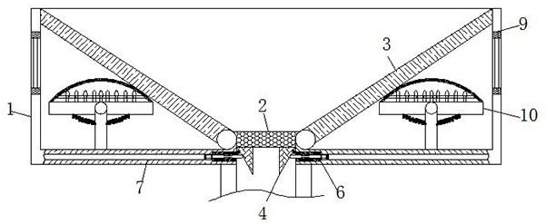
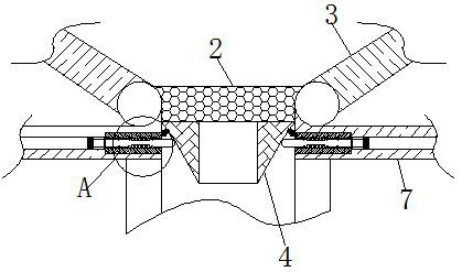
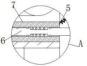
[0023] see Figure 1-6 , a molecular motion suppression device for pesticide packaging, comprising a housing 1, the inside of the housing 1 is fixedly connected with an inlet 2, the surface of the inlet 2 is hinged with a load-bearing plate 3, and the end of the load-bearing plate 3 away from the inlet 2 is connected to the shell The inner wall of the body 1 is slidingly connected, and the lower part of the load-bearing plate 3 is movably connected with a ligh...


PUM


Abstract

The invention relates to the technical field of agricultural chemical packaging, and discloses a molecular motion inhibition device for agricultural chemical packaging. The molecular motion inhibitiondevice for agricultural chemical packaging comprises a shell, wherein the interior of the shell is fixedly connected with an inflow port, the surface of the inflow port is hinged with bearing plates,the bottom of the inflow port is movably connected with baffles, and the surfaces of the baffles are fixedly connected with compression springs; elastic rods are movably connected with the surfaces of the baffles and located below the compression springs; the surface of each elastic rod is in sliding connection with a sliding groove; and when agricultural chemicals flow into the shell, the bearing plates can be extruded to slide on the surfaces of the inner walls of the shell due to the fact that the agricultural chemicals have certain weight, piston rods in the inner walls of the shell are extruded to move downwards, gas is extruded to flow into the sliding grooves, gas blocking blocks in the sliding grooves are pushed by the gas to extrude the elastic rods, the elastic rods extend out of the sliding grooves and push the baffles to move under the clamping of the compression springs, and due to the fact that the elastic rods are symmetrically arranged, the baffles of the sliding grooves are close to each other, the flowing area of the inflow port can be reduced, and thus the effect of reducing the flowing speed of the agricultural chemicals is achieved.

Description

technical field [0001] The invention relates to the technical field of pesticide packaging, in particular to a molecular motion suppression device for pesticide packaging. Background technique [0002] Pesticides refer to chemical agents used in agriculture to prevent and control plant diseases and insect pests and regulate plant growth. Widely used in agricultural, forestry and animal husbandry production, environmental and household sanitation, pest control and epidemic prevention, industrial product mildew and moth prevention, etc. [0003] With the development of science and technology, the packaging technology of pesticides has been automated. When packaging powdered pesticides, at the position of the filling mouth, due to the relatively large force of the powder flowing out, it will be subject to greater force when it comes into contact with the packaging bag. Impact force, this impact force will break up the powder, the powder will form micromolecules, and flow out f...

Claims


Application Information

Patent Timeline
Patent Type & Authority Applications(China)
IPC IPC(8): B65B1/06
CPCB65B1/06
Inventor 宾阳
Owner HUNAN UNIV OF TECH
Learn More