
Flow reducer

A fluid and water accumulation valve technology, applied in the direction of wound drainage device, etc., can solve the problems of non-volume flow setting, shutdown redundancy, and three-layer redundancy complexity, so as to improve health status, avoid deposition, and flexibly treat required effect

Active Publication Date: 2019-12-13
CHRISTOPH MIETHKE
View PDF15 Cites 1 Cited by
  • Summary
  • Abstract
  • Description
  • Claims
  • Application Information

AI Technical Summary

Problems solved by technology

[0026] In summary, the teaching of document US 4676772 concerns the setting of the valve opening pressure, but disadvantageously not the setting of the defined volume flow
Furthermore, the described technique has the disadvantage that setting the valve opening pressure by means of a screwed-in basin can lead to plastic deformation of the diaphragm
[0033] On the downside, the valve opening pressure is only related to the valve orientation in the Earth's gravitational field
[0034] Furthermore, the overvoltage protection unit has the disadvantage that the flow resistance of the second flow path is predefined at the factory by its construction
Therefore, the disclosure has triple redundancy in shutting down
Three layers of redundancy are complex, it hinders the user's ease of understanding and thus violates safe use

Method used


Image

  • Flow reducer
  • Flow reducer
  • Flow reducer

Examples


Embodiment Construction

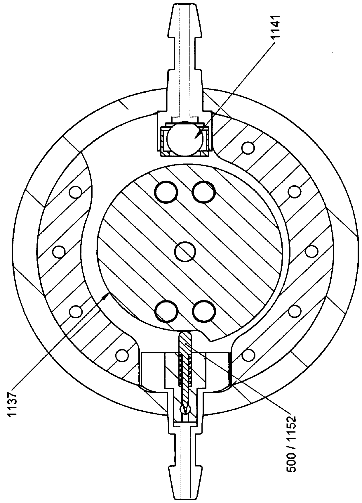
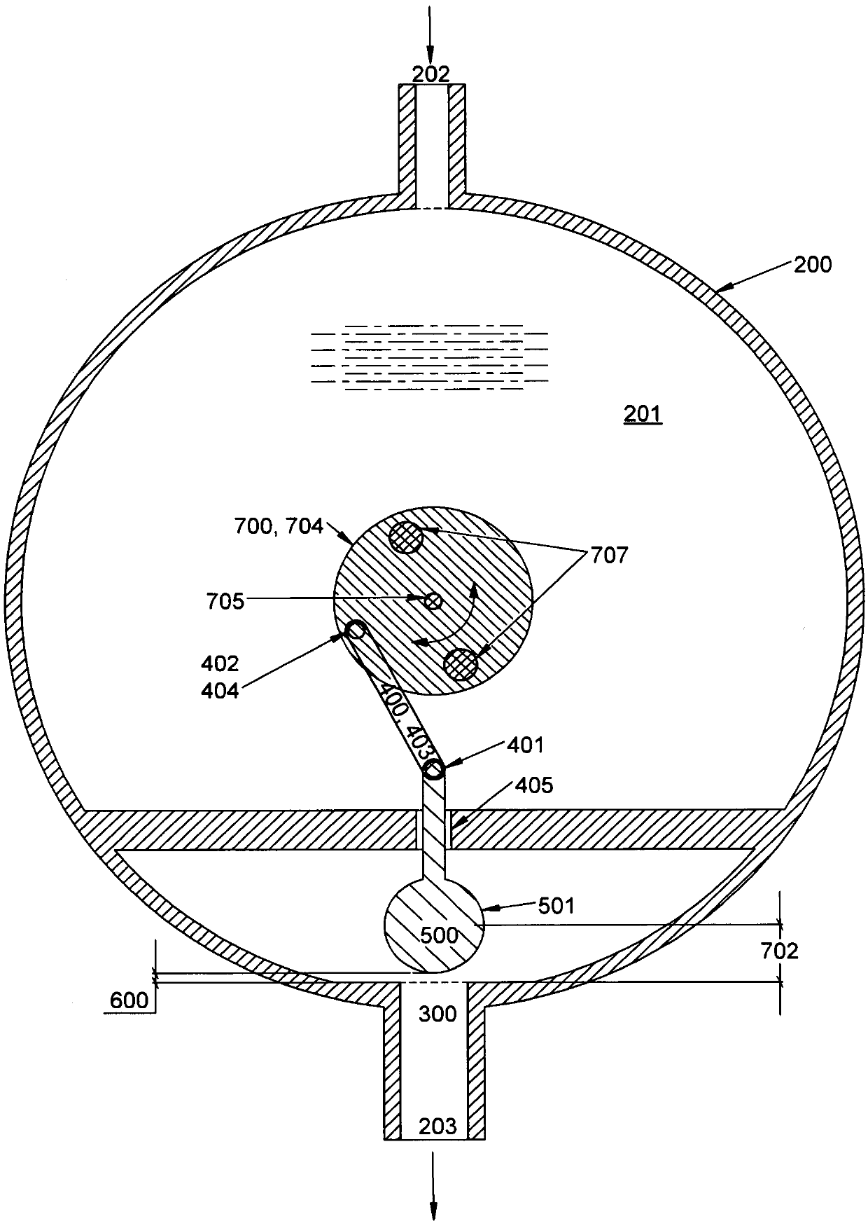
[0177] FIG. 1 shows a hydrocephalus valve 100 according to the invention in its design in a schematic view from above. The figure shows a structure with a housing 200 in which an adjustment unit 700 in the form of a cam disc 704 , a coupling element 400 and a body 500 are mounted. The housing also includes an inlet 202 and an outlet 203 .

[0178] The movement of the cam disc 704 is actively guided centrally in the housing interior 201 by means of the axle 705 , while the body 500 is guided not by the drilled body axis 502 but by its body side surface 503 . FIG. 1 shows that the body 500 is formed as a wedge such that its body side surface 503 tapers from a first body end 504 in the direction of a second body end 505 . FIG. 1 also shows that the shape of the passageway 300 has a wedge or cup shape in cross-section. The wedge 506 is guided in the channel 300 along its body surface by means of a taper of the body side surface 503 corresponding to the taper of the channel.

[...


PUM


Abstract

The invention relates to a hydrocephalus valve for draining fluid from the ventricle systems of patients, said valve having at least one housing with a housing interior; and at least one first passagefor admission and / or discharge, and having at least one body provided in the housing interior, said body being designed to move in at least one direction. At least one adjusting unit is provided. Theinvention aims to improve tried-and-tested existing valves. To achieve this, the adjusting unit is designed to adjust at least one drainage rate in the passage, and to allow the drainage rate to be adjusted between 1 ml per hour and 1000 ml per hour at a pressure at the hydrocephalus valve of 20 cm water column, in order to slow or accelerate, by means of this adjustment, a change in pressure inthe ventricle system that results from the drainage.

Description

technical field [0001] The invention relates to a hydrocephalus valve for draining fluid from the ventricular system of a patient, the valve having at least one housing with an interior of the housing, at least one first passage for entry and / or exit, with an arrangement At least one body in the interior of the housing, wherein the body is designed to be movable in at least one direction, and the valve has at least one adjustment unit. Background technique [0002] People with hydrocephalus have the following medical problems: [0003] In the skull, the brain is surrounded by a specific fluid (fluid). The fluid is constantly produced and absorbed in equal amounts. In the case of hydrocephalus (also known as cerebral edema) disease, this balance is disrupted. Since the skull forms an airtight container, enlargement occurs if more fluid is produced than absorbed. Due to the enlargement, in infants, the sutures fail to fuse, and in adults, intracranial pressure increases. ...

Claims


Application Information

Patent Timeline
Patent Type & Authority Applications(China)
IPC IPC(8): A61M27/00
CPCA61M27/006
Inventor C.梅斯克
Owner CHRISTOPH MIETHKE
Learn More