

Drive device for a movable tappet
A technology of driving device and translational movement, which is applied in the direction of transmission device, electromechanical device, electric component, etc., to achieve the effect of maintenance-free and high manufacturing cost
- Summary
- Abstract
- Description
- Claims
- Application Information
AI Technical Summary
Problems solved by technology
Method used
Image

Examples
Embodiment Construction
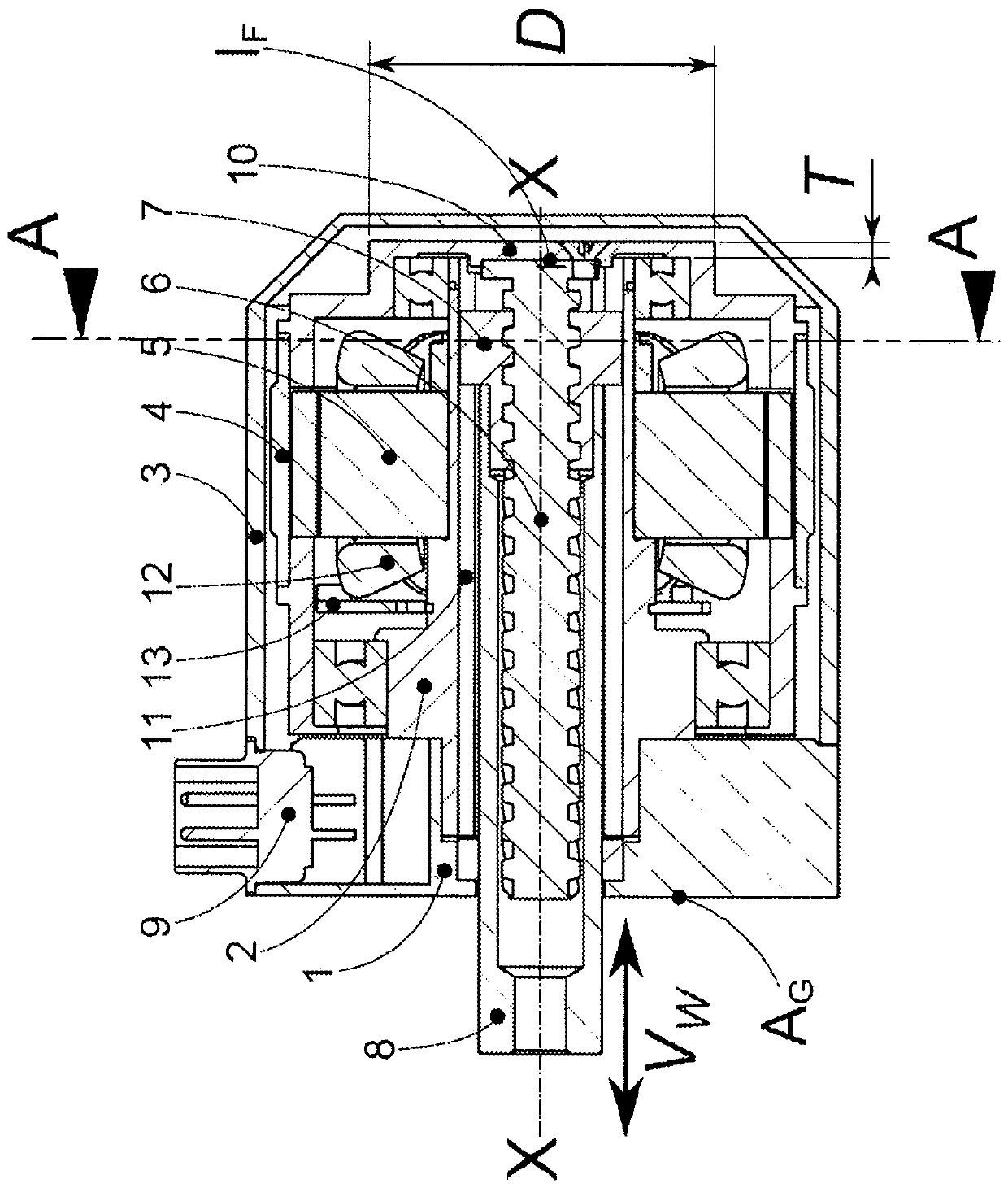
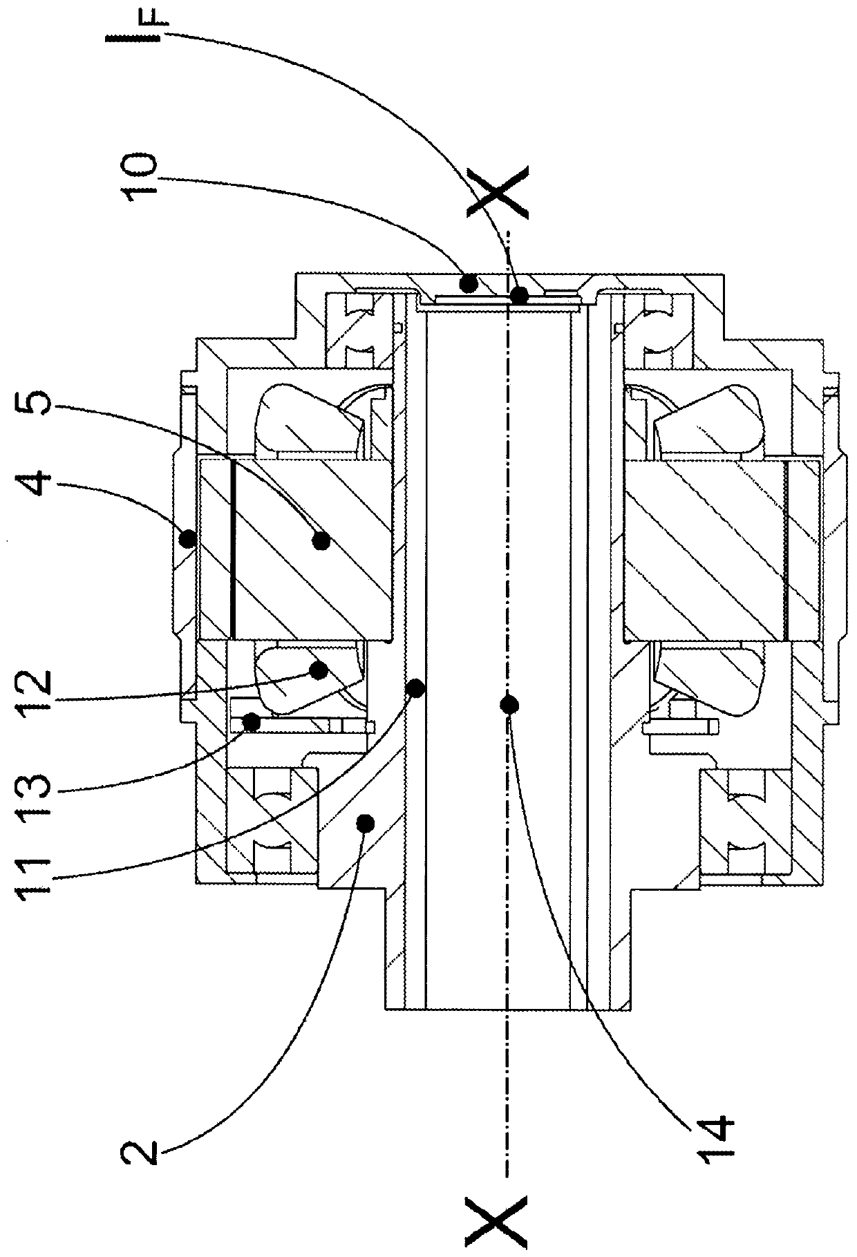
[0071] exist figure 1 A drive device (1') for generating a translational movement of a movable tappet (8) by means of an electromagnetic rotary machine is schematically shown in .
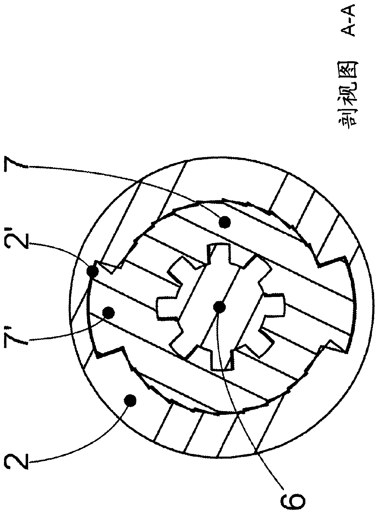
[0072] The drive (1') can comprise, for example, the following components: housing flange (1) with stator tube or stator sleeve (2), protective cover (3), rotor (4), provided with winding (12) The stator (5) or the stator plate group (5), the screw (6) together with the nut (7) and the tappet (8) and the joint (9) for the control and power electronics, the winding and the sensor system (13) Being connected.
[0073] The stator (5) is arranged coaxially with respect to the rotor (4) and comprises at least one pair of moving threads (6, 7) coaxially integrated therein, said pair of moving threads comprising a non-rotatably coupled rotor (4) connected screw (6) and a nut (7) guided linearly in a torsionally fixed manner in the stator sleeve (2), which is preferably rigidly coupled to a tubular tapp...
PUM
 Abstract
Description
Claims
Application Information