Supercharge Your Innovation With Domain-Expert AI Agents!

Fuses with micro switches

A micro-switch and fusing technology, applied in the fields of fusing devices, high-voltage switchgear, and electric power products, can solve the problems of long assembly time, high cost, and inability to close the switch, and achieves reduced production costs, assembly time, and simple structure. Effect

Active Publication Date: 2021-08-27
ABB (SCHWEIZ) AG
View PDF8 Cites 0 Cited by
  • Summary
  • Abstract
  • Description
  • Claims
  • Application Information

AI Technical Summary

Problems solved by technology

[0007] The present invention aims at the problems of complex structure, high cost and long assembly time of the fuse device with micro switch in the prior art. The fuse striker assembly and connecting rod; the fuse striker assembly includes a main shaft, a striker piece and a trigger piece; the striker piece and the trigger piece are radially fixed on the main shaft and can move axially along the main shaft; the interlocking mechanism of the fuse device When one or more fuses are not installed, or when one or more fuses are blown, cooperate with the fuse striker assembly, drive the connecting rod to trigger the micro switch, so that the switch device cannot be closed

Method used


Image

  • Fuses with micro switches
  • Fuses with micro switches
  • Fuses with micro switches

Examples


Embodiment Construction

[0029] A detailed description of alternative embodiments of the present invention is given below with reference to the accompanying drawings.

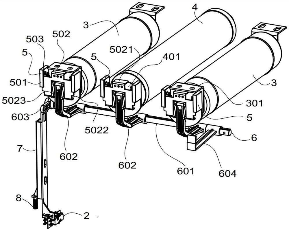
[0030] Figures 2A-2C It is a structural schematic diagram of a best embodiment of the fuse device with micro switch of the present invention; wherein, Figure 2A is a schematic diagram of the three-dimensional structure, Figure 2B for top view, Figure 2A is an axial view.

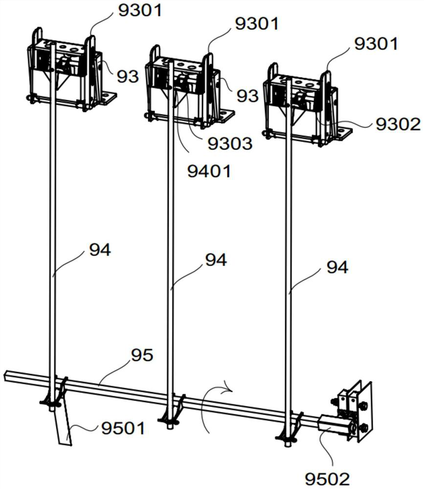
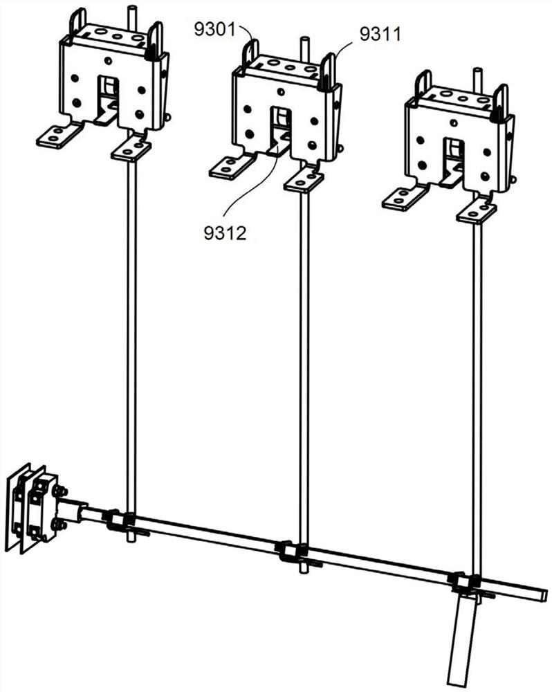
[0031] According to a preferred embodiment of the present invention, the fuse device with a micro switch includes a fuse device interlock mechanism 5 , a fuse striker assembly 6 , a connecting rod 7 and a micro switch 2 .

[0032] The fuse device interlock mechanism 5 cooperates with the fuse striker assembly 6 when one or more fuses are not installed, or when one or more fuses are blown, and drives the connecting rod 7 to trigger the microswitch 2, thereby Make the switchgear unable to close.

[0033] Such as Figure 5 Shown is, according to a preferred em...


PUM


Abstract

A fuse device with a micro switch, comprising a micro switch (2), a fuse device interlock mechanism (5), a fuse striker assembly (6) and a connecting rod (7); the fuse striker assembly (6) includes a spindle (601), a striker piece (602) and a trigger piece (603); the striker piece (602) and the trigger piece (603) are radially fixed on the main shaft (601), and can move axially along the main shaft (601); When one or more fuses are not installed or one or more fuses are blown, the fuse device interlock mechanism (5) cooperates with the fuse striker assembly (6) to trigger the drive link (7) microswitch (2), so that the switching device cannot be closed. The structure of the fuse device with a micro switch is simpler, which effectively reduces the production cost, and the modular components save assembly time.

Description

technical field [0001] The invention belongs to the technical field of electric power products, in particular to the technical field of high-voltage switchgear. In particular, the invention relates to the technical field of a fuse device, an interlock device for installing a fuse and a drive system for blowing a fuse striker. Background technique [0002] In the power system, switch devices are used to control the protected components to perform start-stop operations. Generally, three-phase fuses are configured as short-circuit protection devices. On the one hand, in order to ensure safety, when more than one phase fuse is missing, the switch The device does not allow closing operation, so a fuse installation interlock mechanism is required to ensure this function; on the other hand, when an overcurrent or short circuit fault occurs in the system, the fault current is broken based on the characteristics of the fuse itself. However, when these currents blow one-phase or two-...

Claims


Application Information

Patent Timeline
Patent Type & Authority Patents(China)
IPC IPC(8): H01H9/20
CPCH01H85/306H01H9/104
Inventor 王其亮庄志坚章国龙李巧玲
Owner ABB (SCHWEIZ) AG
Features
  • R&D
  • Intellectual Property
  • Life Sciences
  • Materials
  • Tech Scout
  • Unparalleled Data Quality
  • Higher Quality Content
  • 60% Fewer Hallucinations
Learn More