A rapid coagulation device for small wounds

A wound and fast technology, applied in the mechanical field, can solve the problems of long time consumption, low efficiency, and inability to achieve rapid hemostasis, and achieve the effect of high work efficiency and short time consumption

Active Publication Date: 2021-06-15
中国人民解放军陆军特色医学中心
View PDF5 Cites 0 Cited by
  • Summary
  • Abstract
  • Description
  • Claims
  • Application Information

AI Technical Summary

Problems solved by technology

[0003] The purpose of the present invention is to provide a small-sized wound rapid coagulation device to solve the problem in the above-mentioned background technology that when treating a wound in a hospital, medical personnel need to hold tweezers and other items to treat the wound step by step, and the operation process is inefficient. And it takes a long time to achieve rapid hemostasis

Method used


Image

  • A rapid coagulation device for small wounds
  • A rapid coagulation device for small wounds
  • A rapid coagulation device for small wounds

Examples


Embodiment 1

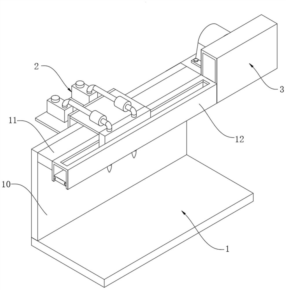
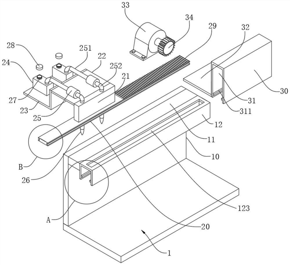
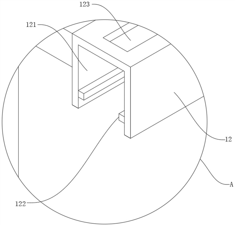
[0032] A small wound rapid coagulation device, such as Figure 1 to Figure 4 As shown, the base plate 1 is included, the base plate 1 is tightly welded with a vertical plate 10 distributed vertically, and the front side of the vertical plate 10 is tightly welded with a top plate 11 distributed horizontally, and the top plate 11 and the base plate 1 are located at On the same side of the vertical plate 10, a rectangular block 12 is tightly welded on the top plate 11, and a first rectangular groove 121 communicating with the outside world is also provided in the rectangular block 12, and the left and right sides of the first rectangular groove 121 are closely connected. The first slider 122 is welded, the top wall of the first rectangular groove 121 is provided with a first chute 123 communicating with the outside world, the rectangular block 12 is provided with a spraying treatment device 2, and the spraying treatment device 2 includes a The rectangular plate 20 in the first re...

Embodiment 2

[0041] As the second embodiment of the present invention, in order to be able to process the waste liquid for cleaning wounds, avoiding the random discharge of untreated waste liquid and causing pollution to the environment, the inventors made improvements to the bottom plate 1 as a preferred implementation For example Figure 5 and Figure 6 As shown, the base plate 1 is also provided with a number of water holes 4 arranged in a matrix and connected to the outside world. The upper surface of the base plate 1 is also tightly welded with a baffle plate 40, and the lower surface of the base plate 1 is tightly welded with a waste liquid collection. Case 41, water hole 4 is connected with waste liquid collection box 41, and waste liquid treatment box 42 is tightly welded on the back side of waste liquid collection box 41, is provided with cavity 421 in the waste liquid treatment box 42, and cavity 421 The filter screen 422 that is vertically distributed is tightly bonded on the w...

Embodiment 3

[0049] As a third embodiment of the present invention, in order to bandage the wound that has been hemostasis, and to avoid the growth of more bacteria on the wound healing adhesive plaster 541, causing secondary infection of the patient's wound, the inventor made a further step on the bottom plate 1 Improvement, as a preferred embodiment, such as Figure 7 and Figure 8 As shown, the right side of the bottom plate 1 is tightly welded with steel plates 5 that are distributed horizontally, and the steel plates 5 are provided with two mutually symmetrical arc blocks 50. A shaft hole 51 communicating with the outside world is provided, and a cutting blade 52 is tightly welded on one of the arc-shaped blocks 50. The cutting blade 52 is located between two arc-shaped blocks 50, and a rotating shaft is arranged between the two arc-shaped blocks 50 54, the end of the rotating shaft 54 ​​is located in the shaft hole 51, the rotating shaft 54 ​​is connected with the shaft hole 51, the...


PUM


Abstract

The invention relates to the field of mechanical technology, in particular to a small wound rapid coagulation device, which includes a base plate, on which vertical plates distributed vertically are tightly welded, and vertical plates distributed horizontally are tightly welded on the front side of the vertical plate. Top plate, a rectangular block is tightly welded on the top plate, and a spraying treatment device is arranged on the rectangular block. A fixed block on the right side of a rectangular block. The invention saves time and labor, is simple and quick to operate, improves the work efficiency of hemostasis, and reduces the burden of medical staff.

Description

technical field [0001] The invention relates to the technical field of machinery, in particular to a rapid coagulation device for small wounds. Background technique [0002] In daily life, bumps will inevitably occur on human body parts. When bumps occur, wounds will be left on the bumped parts of the human body. In severe cases, the wounds will bleed. Therefore, it is necessary to treat the wounds in time. When treating the wound, it is necessary for medical staff to hold tweezers and other items to treat the wound. This operation process is inefficient and time-consuming, and cannot achieve the purpose of rapid hemostasis. In view of this, we propose a rapid coagulation device for small wounds. Contents of the invention [0003] The purpose of the present invention is to provide a small-sized wound rapid coagulation device to solve the problem in the above-mentioned background technology that when treating a wound in a hospital, medical personnel need to hold tweezers a...

Claims


Application Information

Patent Timeline
Patent Type & Authority Patents(China)
IPC IPC(8): A61M35/00A61F15/00A61L2/10
CPCA61F15/001A61L2/10A61L2202/11A61L2202/121A61L2202/23A61M35/00
Inventor 刘银春
Owner 中国人民解放军陆军特色医学中心
Why Eureka
Try Eureka