Underwater robot support and underwater robot

The technology of an underwater robot and a bracket plate is applied in the directions of underwater ships, underwater operation equipment, motor vehicles, etc., which can solve the problem of low shooting accuracy, and achieve the effects of convenient carrying, simple assembly process, and enlarged shooting range.

Inactive Publication Date: 2019-12-17
HOHAI UNIV
View PDF9 Cites 4 Cited by
  • Summary
  • Abstract
  • Description
  • Claims
  • Application Information

AI Technical Summary

Problems solved by technology

[0003] The purpose of the present invention is to overcome the shortcomings of the low shooting accuracy of underwater robot cameras in the prior art, and provide a support for underwater robots. The technical solution is as follows:

Method used


Image

  • Underwater robot support and underwater robot
  • Underwater robot support and underwater robot
  • Underwater robot support and underwater robot

Examples


Embodiment 1

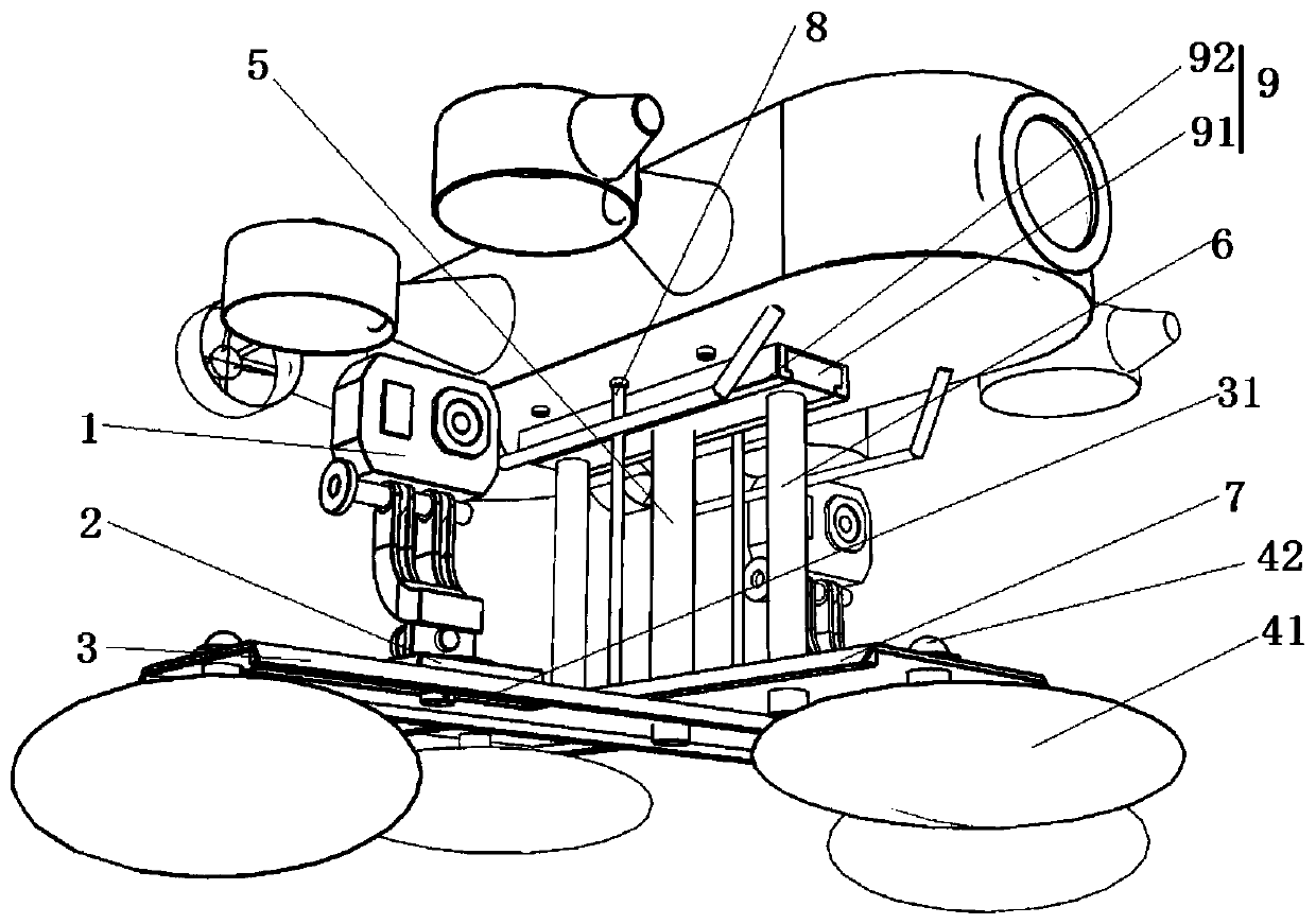
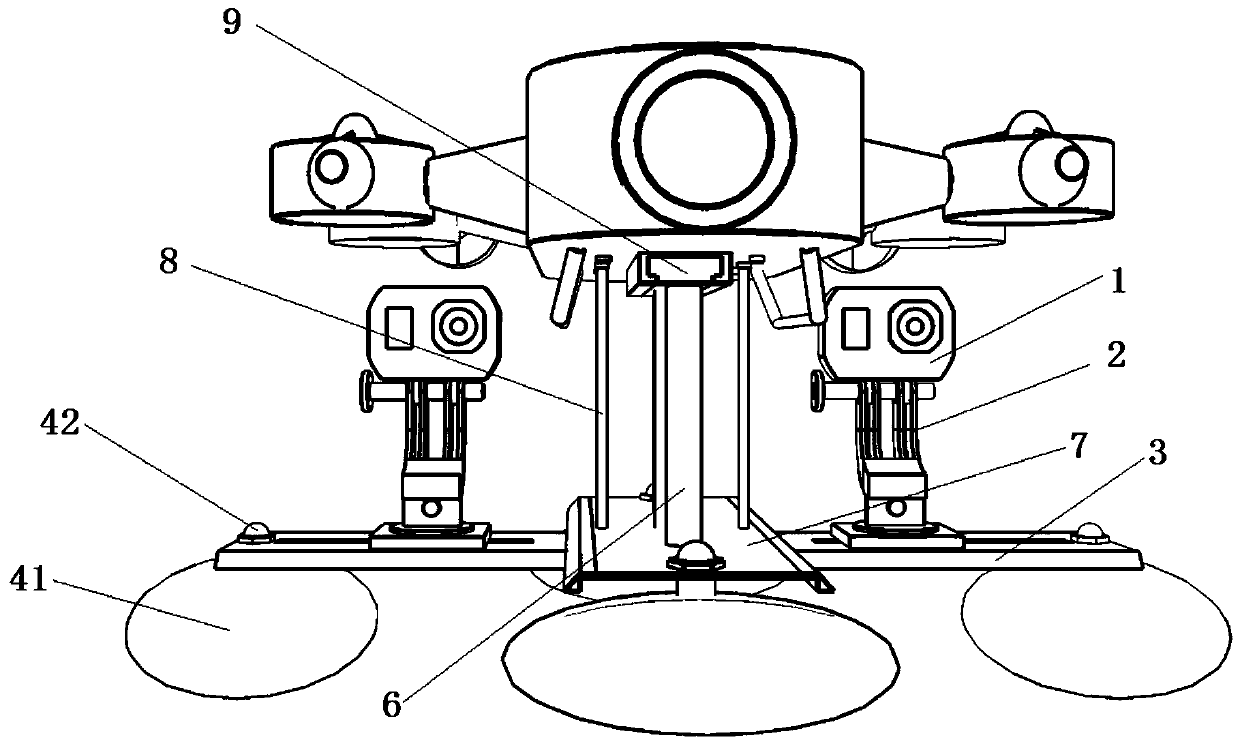
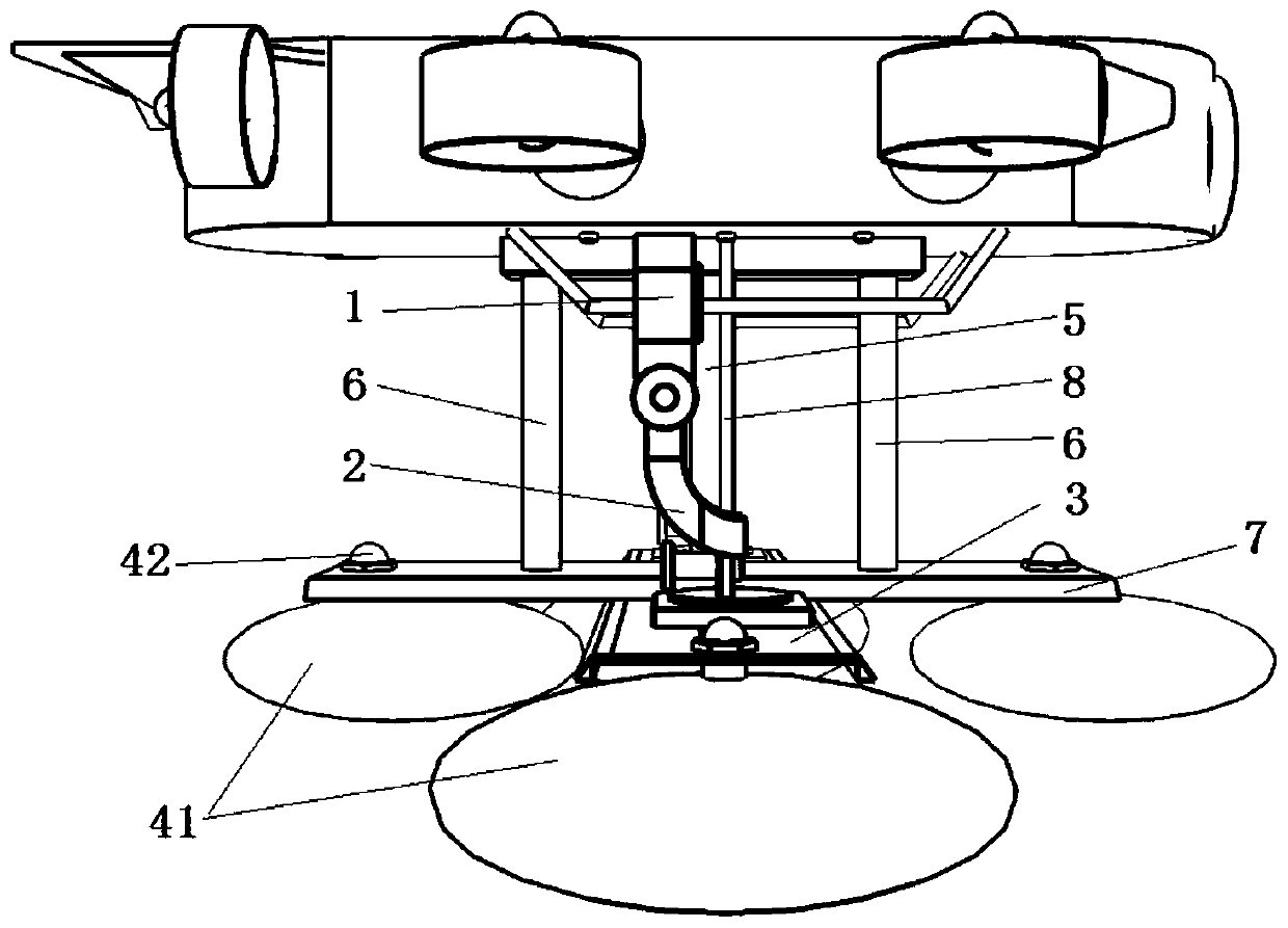
[0026] Such as Figure 1 to Figure 5 As shown, the underwater robot support includes a first pillar 5, the top of the first pillar 5 is fixedly connected to the underwater robot, the bottom of the first pillar 5 is fixedly connected to the first support plate 3, and the two ends of the first support plate 3 are respectively The binocular camera 1 is slidably arranged, and a balance device 4 is fixed on the first support plate 3 through a connecting piece 42.

[0027] Specifically, the balancing device 4 includes four floating balls 41 arranged in four directions: front, rear, left, and right, and the floating balls 41 are fixedly connected to the first support plate 3. The floating ball 41 has a variety of different models. The floating ball 41 can be detachably installed to facilitate the replacement of different models of the floating ball 41 to match and balance the weight of the bracket and the weight of the binocular camera 1 of different models, so that the underwater robot ...

Embodiment 2

[0036] Such as Figure 6 to Figure 11 , Underwater robot support, including the first pillar 5, the top of the first pillar 5 is fixedly connected to the underwater robot, the bottom of the first pillar 5 is fixedly connected to the first support plate 3, and the two ends of the first support plate 3 are slidably arranged For the binocular camera 1, a balancing device 4 is fixed on the first support plate 3 through a connecting piece 42.

[0037] Specifically, the balancing device 4 includes four floating balls 41 arranged in four directions: front, rear, left, and right, and the floating balls 41 are fixedly connected to the first support plate 3. The floating ball 41 has a variety of different models. The floating ball 41 can be detachably installed to facilitate the replacement of different models of the floating ball 41 to match and balance the weight of the bracket and the weight of the binocular camera 1 of different models, so that the underwater robot can be The suspensi...


PUM


Abstract

The invention discloses an underwater robot support which comprises a first supporting column. The top of the first supporting column is fixedly connected with an underwater robot, the bottom of the first supporting column is fixedly connected with a first support plate, the two ends of the first support plate are slidably provided with binocular cameras respectively, and a balance device is fixedto the first support plate through a connecting piece. The balance device comprises four floating balls arranged in the front, rear, left and right directions, and the floating balls are fixedly connected with the first support plate. The bottoms of the binocular cameras are provided with supports, and slide ways for the supports to slide are formed in the first support plate. A sliding rail is fixed at the top of the first supporting column, and the sliding rail is embedded into a sliding groove in the underwater robot to be fixed. The invention further discloses the underwater robot. According to the underwater robot support, the shooting range of the underwater robot is expanded, the underwater robot can dive to any depth and position for shooting, the positions and angles of the two cameras can be independently adjusted, clear images with small errors can be obtained, and the device is simple in assembly process and convenient to carry.

Description

Technical field [0001] The invention relates to an underwater robot support and an underwater robot, in particular to an underwater robot binocular camera support, belonging to the technical field of underwater robots. Background technique [0002] With the development of technology, automation, and intelligence in tunnel monitoring, in the process of tunnel monitoring, various relevant departments have begun to choose to use robots instead of manpower in the field of monitoring, and intelligent processing instead of manual monitoring. However, in actual use, the camera accuracy and shooting position are difficult to meet the requirements accurately. Especially in the underwater tunnel inspection, the binocular camera is not portable and the detection method is limited. Therefore, it is urgent to design a connection device for connecting the robot and the binocular camera. , The robot drives the accurate binocular camera to shoot different angles and different positions for diffe...

Claims


Application Information

Patent Timeline
Patent Type & Authority Applications(China)
IPC IPC(8): B63C11/52B63G8/38
CPCB63C11/52B63G8/38
Inventor 雷冬荆晓晖朱飞鹏白鹏翔张峰瑞卢太奇
Owner HOHAI UNIV
Why Eureka
Try Eureka