Undercarriage part heat treatment distortion control device and method

A technology of heat treatment deformation and control device, which is applied in heat treatment furnaces, heat treatment equipment, quenching devices, etc., to meet the requirements of deformation, smooth flow, and reduce deformation.

Active Publication Date: 2019-12-17
LANDING GEAR ADVANCED MFG
View PDF5 Cites 7 Cited by
  • Summary
  • Abstract
  • Description
  • Claims
  • Application Information

AI Technical Summary

Problems solved by technology

[0007] In view of the above-mentioned problems of parts clamping and heat treatment deformation, the purpose of the present invention is to provide a landing gear with an inverted "y" clamping method, which make...

Method used


Image

  • Undercarriage part heat treatment distortion control device and method
  • Undercarriage part heat treatment distortion control device and method
  • Undercarriage part heat treatment distortion control device and method

Examples


Embodiment Construction

[0037] The present invention will be described in detail below with reference to the accompanying drawings and examples. It should be noted that, in the case of no conflict, the embodiments of the present invention and the features in the embodiments can be combined with each other. For the convenience of description, if the words "up", "down", "left" and "right" appear in the following, it only means that the directions of up, down, left and right are consistent with the drawings themselves, and do not limit the structure.

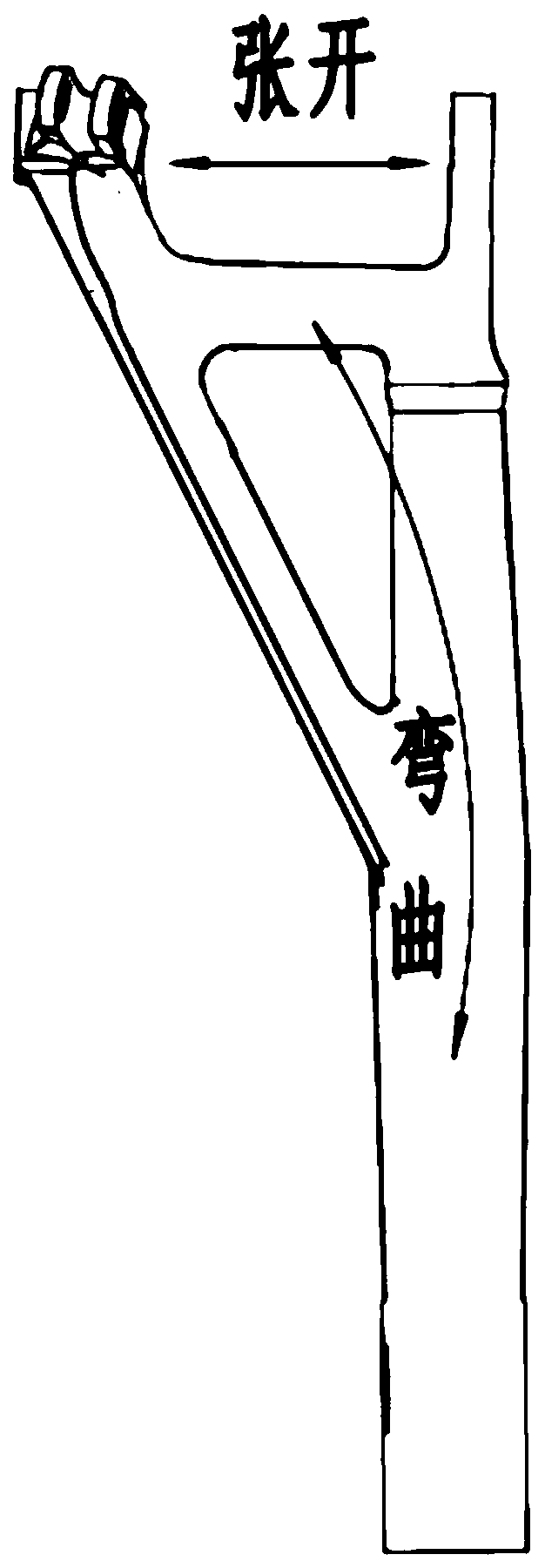
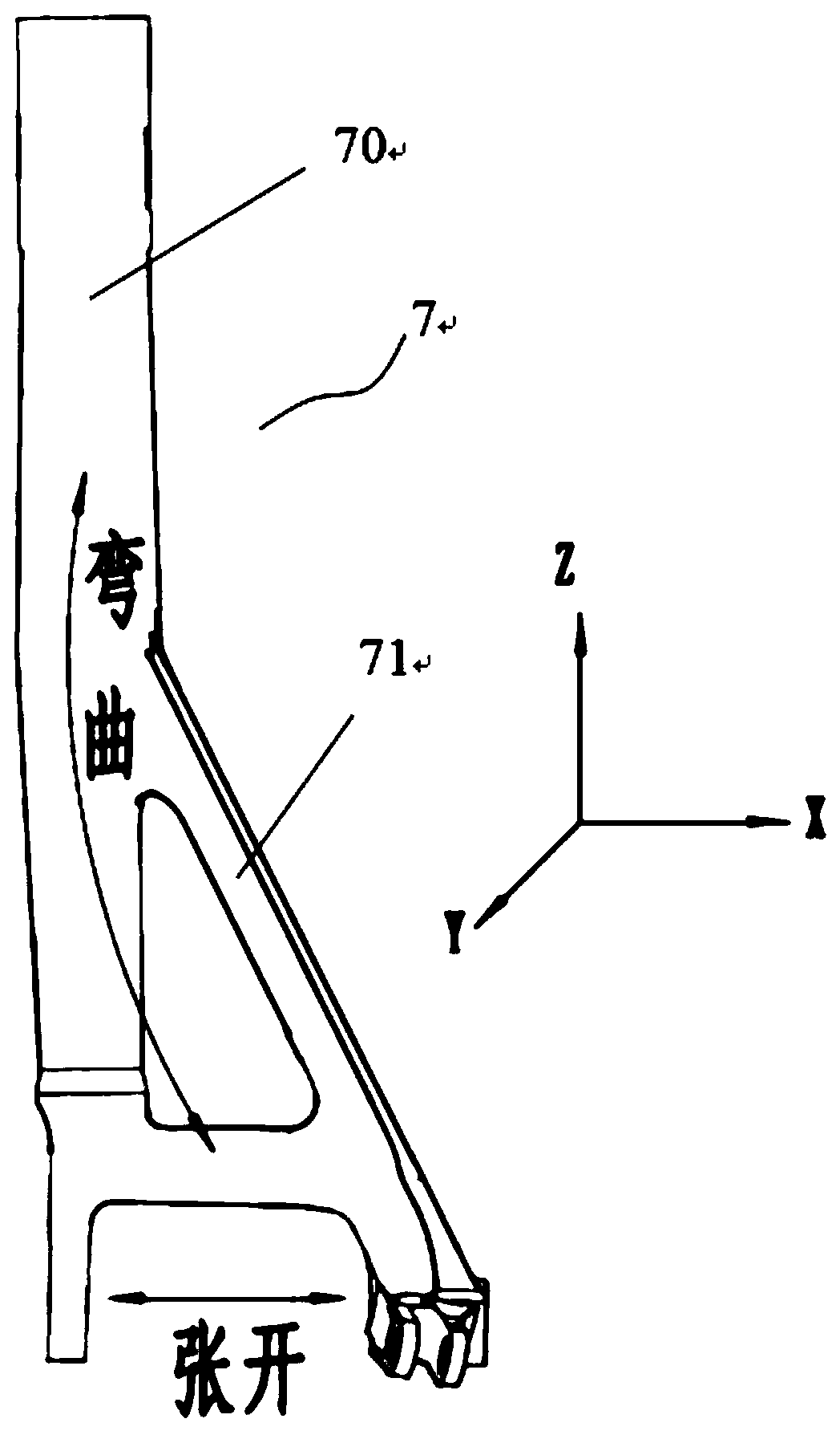
[0038] Such as Figure 1~2 As shown, the landing gear part 7 provided in this embodiment includes a Y-shaped structure formed by a vertically arranged main cylinder 70 and branches 71 inclined from the main cylinder 70 . The main cylinder 70 is provided with an inclination angle α adjacent to the branch 71 .

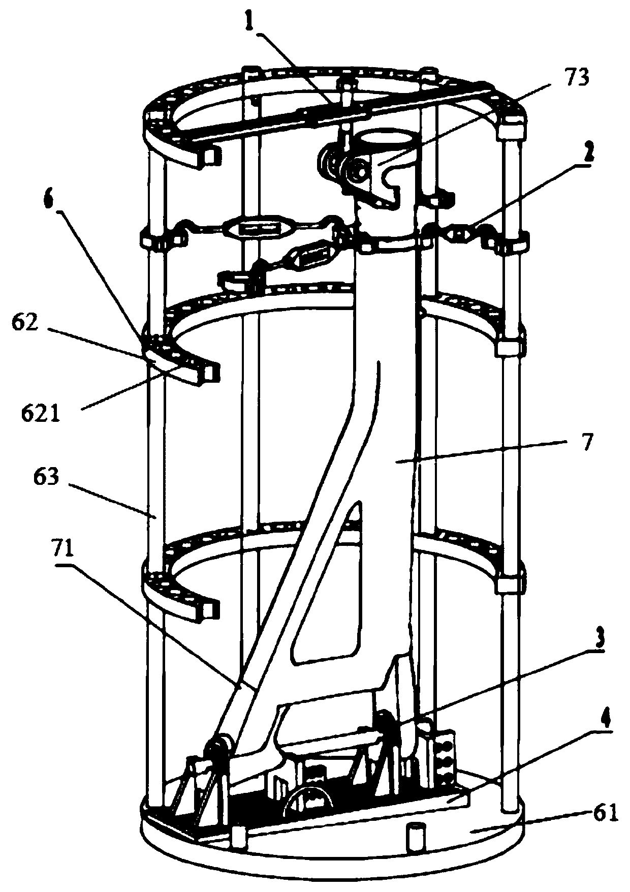
[0039] Such as figure 2 As shown, a heat treatment deformation control device for landing gear parts provided in this embodiment includes a hea...


PUM


Abstract

The invention provides an undercarriage part heat treatment distortion control device and method. The undercarriage part heat treatment distortion control device comprises a heat treatment frame, a top adjusting module arranged at the upper end of the heat treatment frame, a supporting base module arranged at the bottom of the heat treatment frame, an anti-expansion control module matched with thesupporting base module and a horizontal adjusting module fixed to the heat treatment frame in a scalloped manner. The top adjusting module and the supporting base module are located in a hollow structure of the heat treatment frame, and the control directions of the top adjusting module and the supporting base module are vertical. The anti-expansion control module and the horizontal adjusting module are located in the hollow structure of the heat treatment frame, and the control directions of the anti-expansion control module and the horizontal adjusting module are horizontal. Compared with the prior art, by means of combined adjustment of the modules, the problem of unstability generated by stress unbalance in the part transferring process is solved, oil input is carried out in an inverted-y manner in the vacuum heat treatment quenching process of parts, it is guaranteed that a barrel is in a vertical state, and quenching oil flowing is convenient.

Description

technical field [0001] The invention relates to the technical field of metal heat treatment processing, in particular to a vacuum quenching heat treatment technology, and further relates to a heat treatment deformation control device and control method for landing gear parts. Background technique [0002] Metal workpiece heat treatment is to put the metal workpiece into the heating device, heat it to a specific temperature for a specific time, and then cool it to change the internal structure of the metal to achieve the purpose of improving the mechanical, physical and chemical properties of the material. During the heat treatment process, the specific volume changes due to the transformation of the structure, resulting in volume expansion. At the same time, the elastic and plastic deformation caused by the uneven wall thickness of the workpiece changes the shape of the part to varying degrees, resulting in heat treatment deformation. Some miscellaneous structural parts with...

Claims


Application Information

Patent Timeline
IPC IPC(8): C21D9/00C21D1/63
CPCC21D1/63C21D9/0025
Inventor 熊诵涛冯抗屯秦楚山付隔清王海艳贺亚勇
Owner LANDING GEAR ADVANCED MFG
Why Eureka
Try Eureka