Intelligent traction moving plate applied to erecting power transmission line

A power transmission line, intelligent technology, applied in the direction of overhead line/cable equipment, etc., can solve the problem of inconvenient use of running boards, and achieve the effect of saving space, convenient use, and convenient maintenance

Pending Publication Date: 2019-12-17
ANHUI ELECTRIC POWER TRANSMISSION & TRANSFORMATION ENG +1
View PDF1 Cites 0 Cited by
  • Summary
  • Abstract
  • Description
  • Claims
  • Application Information

AI Technical Summary

Problems solved by technology

[0004] Aiming at the defect in the prior art that the running board needs to be disassembled when the instrument is inspected and maintained, resulting in inconvenient use of the running board, the present invention provides an intelligent traction running board used in erecting transmission lines

Method used


Image

  • Intelligent traction moving plate applied to erecting power transmission line
  • Intelligent traction moving plate applied to erecting power transmission line
  • Intelligent traction moving plate applied to erecting power transmission line

Examples


Embodiment 1

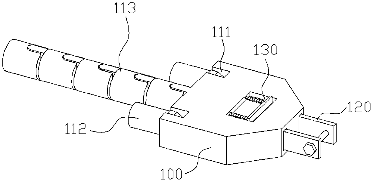
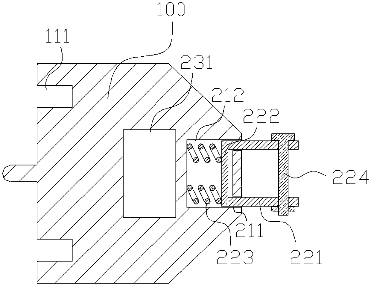
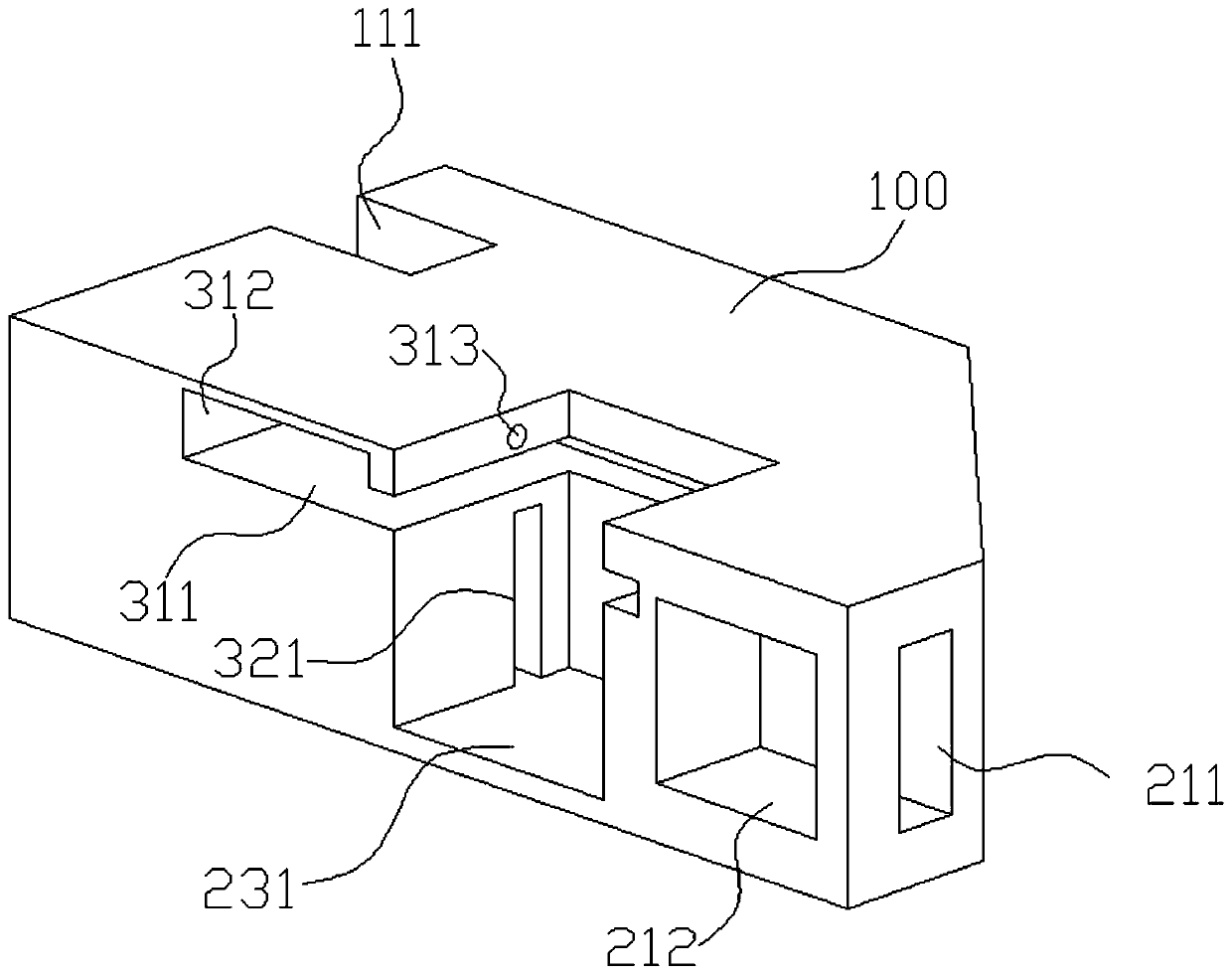
[0035] Such as Figure 1-8 As shown, this embodiment provides an intelligent traction walking board applied to erecting power transmission lines, which includes a walking board main body 100, and the left side of the walking board main body 100 is provided with snap-in slots 111 at the front and rear ends. A rotary connector 112 for connecting wires is hinged in the clamping groove 111. The right side of the walking board main body 100 and located at the front and rear ends are provided with movable grooves 211 along the left and right directions, and the walking board main body 100 is provided with communicating movable grooves The cavity 212 of 211; the right side of the walking plate main body 100 is provided with a traction mechanism 120 for connecting the traction line, the traction mechanism 120 includes a movable plate 221 located in the corresponding movable groove 211, and a movable plate 221 is connected between the movable plates 221 and is located in the cavity. Th...


PUM


Abstract

The invention relates to the technical field of power transmission line pay-off equipment, and discloses an intelligent traction moving plate applied to erecting a power transmission line. The intelligent traction moving plate comprises a moving plate body. The left side surface of the moving plate body is provided with clamping grooves which are arranged on the front and rear ends. A rotary connector used for connecting a lead is hinged in each clamping groove. The right side surface of the moving plate body is provided with movable grooves which are arranged on the front and rear ends alongthe left-and-right direction. A cavity communicated with the movable grooves is arranged in the moving plate body. A traction mechanism used for connecting a traction line is arranged on the right side surface of the moving plate body. The traction mechanism comprises movable plates which are located in the corresponding movable grooves. A baffle plate located in the cavity is connected between the movable plates. The movable plates are connected through bolts outside the moving plate body. A first spring is connected between the baffle plate and the side wall of the cavity, and the first spring is used for pulling the baffle plate to move into the cavity. With application of the structure, the connection between the moving plate body and the traction rope is more convenient and the effectof reducing the space occupied by the moving plate body is reduced.

Description

technical field [0001] The invention relates to the technical field of power transmission line pay-off equipment, in particular to an intelligent traction board applied in erecting power transmission lines. Background technique [0002] The traction board is an essential tool for the construction of multi-split overhead wire tension wires in high-voltage transmission lines. Connected to the tail of the traction board, the traction board is pulled forward by a traction wire rope. When the traction board passes through the pay-off pulley on each base tower, each towed wire can fall to the corresponding pay-off pulley wheel in the slot. The running board is at a high altitude during work, and it is impossible to accurately judge the position of the running board and the working status of the running board. It is often prone to rollover of the running board, the installation of the pay-off block, etc., and it takes a lot of manpower and material resources to correct it, which i...

Claims


Application Information

Patent Timeline
Patent Type & Authority Applications(China)
IPC IPC(8): H02G1/04
CPCH02G1/04
Inventor 马晓飞汪宏春周宜开徐鹏飞窦鑫周浩赵瑞旺王超谢立超
Owner ANHUI ELECTRIC POWER TRANSMISSION & TRANSFORMATION ENG
Why Eureka
Try Eureka