Conveying-reliable cooking utensil
A technology for cooking utensils and feeding materials, applied in cooking utensils, household utensils, kitchen utensils, etc., can solve the problems of inaccurate material quantity measurement, screw lock, affecting feeding efficiency, etc., shortening the feeding distance and improving the feeding efficiency. The efficiency of the material and the effect of reducing the load
- Summary
- Abstract
- Description
- Claims
- Application Information
AI Technical Summary
Problems solved by technology
Method used
Image
Examples
Embodiment 1
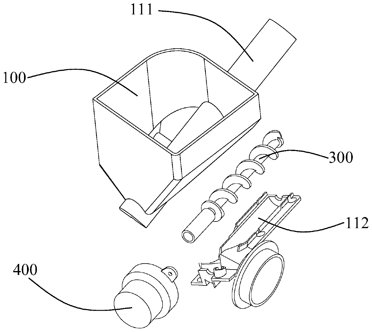
[0045] A cooking utensil is provided in this embodiment, such as Figure 3-8 As shown, the cooking utensil includes a body (not shown in the figure), and the body is provided with a bin assembly, and the bin assembly includes a bin 100, a feeding cavity 200 and a screw 300 with a delivery screw 310. Specifically, the silo 100 is formed with a material storage cavity for storing materials, and the two ends of the material delivery cavity 200 are respectively provided with a feed port 210 and a discharge port 220, and the material delivery cavity 200 is arranged in the silo The bottom of 100 communicates with the material storage cavity of silo 100 through feed port 210, and screw rod 300 is arranged on the interior of material delivery cavity 200 to transfer material from feed port end to discharge port end, and the conveying screw 310 of screw rod 300 is connected with A material passage is formed between the feeding chambers 200, and the volume of the material passage between...
Embodiment 2
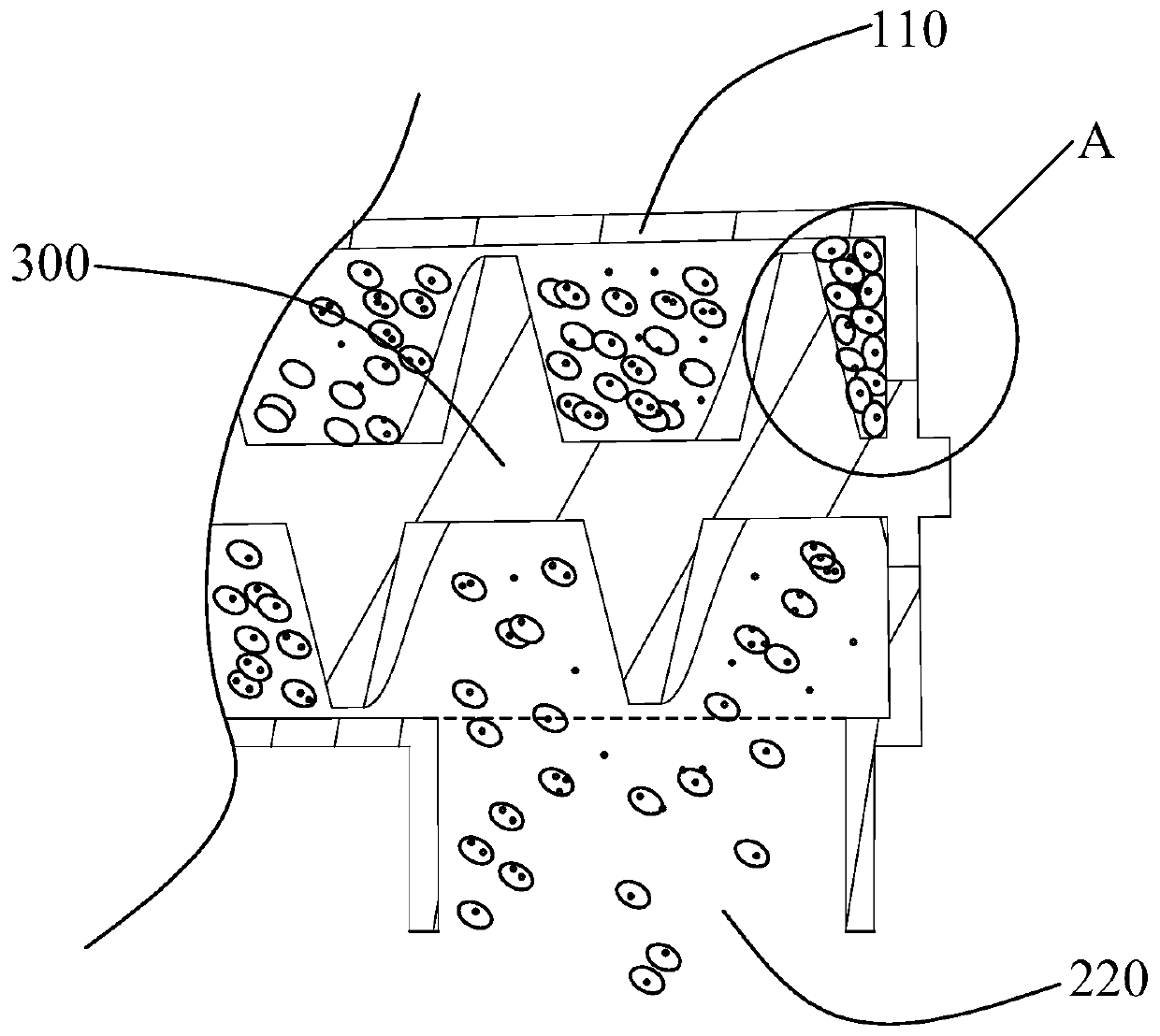
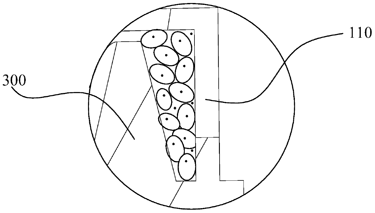
[0060] Such as Figure 9-11 As shown, the difference between the present embodiment and the first embodiment is that the height of the conveying screw 310 of the screw 300 corresponding to the discharge port 220 decreases in the conveying direction. Specifically, such as Figure 10 As shown in , h1>h2.
[0061] Compared with the existing technology, by gradually reducing the height of the conveying screw corresponding to the discharge port along the conveying direction, on the one hand, the feeding distance of the material in the conveying direction is shortened, thereby improving the feeding efficiency ; On the other hand, due to the shortened feeding distance, under the same conditions, the amount of material that the screw conveying screw acts on is relatively reduced, thereby reducing the load on the screw. And, if Figure 11 As shown, compared with the method of Embodiment 1, the material can be made to fall uniformly in the feeding direction and pass through the disch...
Embodiment 3
[0064] Such as Figure 12 , 13 As shown, the difference between this embodiment and Embodiments 1 and 2 is that: the head end of the conveying screw 310 is located in the range of the feed inlet. In this way, the occurrence of material jamming when the screw is reversed is prevented.
[0065] In an implementation manner of this embodiment, the first section of the conveying screw maintains a preset distance L1 from the head end of the screw.
[0066] In another optional implementation manner of this embodiment, the head end of the conveying screw on the screw 300 increases from the head end of the screw.
PUM
 Abstract
Description
Claims
Application Information
 - R&D
- Intellectual Property
- Life Sciences
- Materials
- Tech Scout
- Unparalleled Data Quality
- Higher Quality Content
- 60% Fewer Hallucinations
Browse by: Latest US Patents, China's latest patents, Technical Efficacy Thesaurus, Application Domain, Technology Topic, Popular Technical Reports.
© 2025 PatSnap. All rights reserved.Legal|Privacy policy|Modern Slavery Act Transparency Statement|Sitemap|About US| Contact US: help@patsnap.com


