Device used for production of solar water heaters

A technology of solar water heaters and equipment, applied in heat exchange equipment, metal processing equipment, feeding devices, etc., can solve the problems of inability to realize automation, great safety hazards, low stamping efficiency, etc., achieve automation, reduce manpower and material resources, The effect of easy operation

Inactive Publication Date: 2019-12-20
平庆义
View PDF6 Cites 5 Cited by
  • Summary
  • Abstract
  • Description
  • Claims
  • Application Information

AI Technical Summary

Problems solved by technology

[0004] The purpose of the present invention is to solve the problems in the prior art that solar brackets are generally clamped and fixed manually during stamping production, which has a large safety hazard, low stamping efficiency, a lot of manpower wasted, and automation cannot be realized, so it cannot meet the requirements. The shortcomings of people's needs, and a kind of solar water heater production equipment

Method used


Image

  • Device used for production of solar water heaters
  • Device used for production of solar water heaters
  • Device used for production of solar water heaters

Examples


Embodiment 1

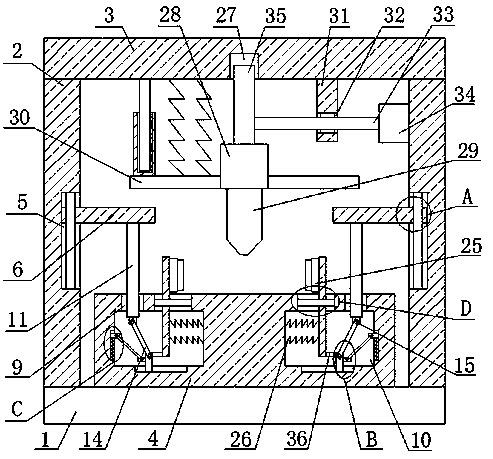
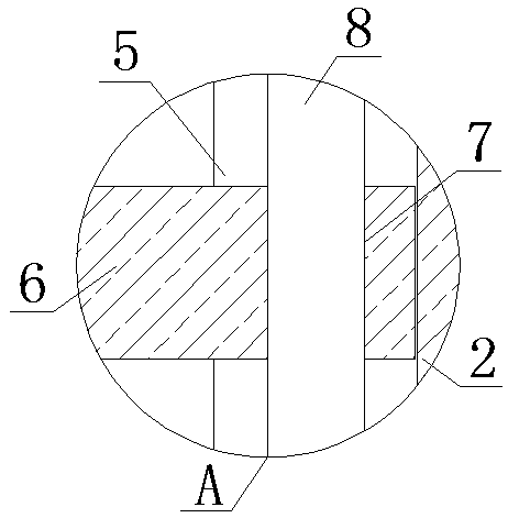
[0028] refer to Figure 1-5 , a kind of solar water heater production equipment, comprising a fixed base 1, fixed columns 2 are fixedly installed on both sides of the top of the fixed base 1, the top of the two fixed columns 2 is fixedly installed with the same fixed plate 3, the top of the fixed base 1 A placement platform 4 between the two fixed columns 2 is fixedly installed, and the sides of the two fixed columns 2 close to each other are provided with a moving groove 5, and a moving plate 6 is slidably installed in the two moving grooves 5, and the two moving A limit hole 7 is provided on the plate 6, and a limit rod 8 is slidably installed in the two limit holes 7, and the top and bottom ends of the limit rod 8 are respectively fixed to the top inner wall and the bottom inner wall of the corresponding moving groove 5. connect.

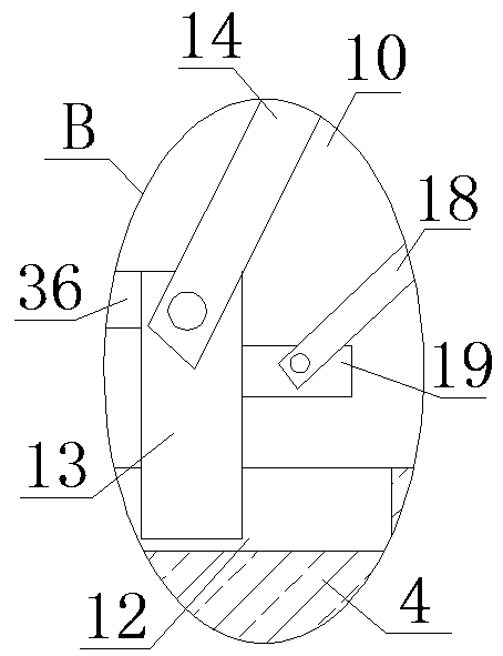
[0029] In the present invention, two sliding holes 9 are provided on the top of the placing table 4, installation grooves 10 are provided on th...

Embodiment 2

[0039] refer to Figure 1-5 , a kind of equipment for producing solar water heaters, comprising a fixed base 1, both sides of the top of the fixed base 1 are fixedly connected with fixed columns 2 by bolts, and the tops of the two fixed columns 2 are fixedly connected with the same fixed plate 3 by bolts, fixed The top of the seat 1 is fixedly connected with a placement platform 4 between the two fixed columns 2, and the sides of the two fixed columns 2 close to each other are provided with a moving slot 5, and a moving slot 5 is slidably installed in the two moving slots 5. plate 6, two moving plates 6 are provided with limit holes 7, and limit rods 8 are slidably installed in the two limit holes 7, and the top and bottom ends of the limit rods 8 are respectively connected to the corresponding moving slots 5. The top inner wall and the bottom inner wall are fixedly connected, and the limit rod 8 limits the position of the moving plate 6 .

[0040] In the present invention, t...


PUM


Abstract

The invention belongs to the field of water heater production and particularly relates to a device used for production of solar water heaters. According to the problems that when an existing solar support is subjected to punching production, manual work is usually adopted for clamping and fixing, large potential safety hazards exist, the punching efficiency is low, a large amount of labor force iswasted, automation cannot be achieved, and the requirements of people cannot be met, the following scheme is put forwards at present. According to the scheme, the device comprises a fixing seat. Fixing pillars are fixedly installed on the two sides of the top of the fixing seat. The same fixing plate is commonly installed at the top ends of the two fixing pillars. A carrying table located betweenthe two fixing pillars is fixedly installed on the top of the fixing seat. Moving grooves are formed in the sides, close to each other, of the two fixing pillars. The device is simple in structure and convenient to operate, a solar panel on a carrying table can be rapidly and conveniently fixed and clamped, the solar panel can be punched conveniently, automation is achieved, labor force and material resources are reduced, the punching efficiency is improved, and the requirements of people are met.

Description

technical field [0001] The invention relates to the technical field of water heater production, in particular to equipment for solar water heater production. Background technique [0002] A solar water heater is a heating device that converts sunlight energy into heat energy. It heats water from low temperature to high temperature to meet the needs of hot water in people's life and production. Solar water heaters are installed with mounting brackets for support. Publication number CN207255667U Disclosed is a solar water heater bracket production line. The upper part of the traction device is equipped with a pinch roller, the lower part is equipped with a traction roller, and the front end of a fixed-length cutting machine is equipped with a length sensor of a metal plate, a length sensor, a traction motor of the traction device, The punching cylinder of the punching machine and the control valve of the cutter cylinder of the fixed-length cutting machine are connected to the ...

Claims


Application Information

Patent Timeline
Patent Type & Authority Applications(China)
IPC IPC(8): B21D22/02B21D43/00B21D53/04
CPCB21D22/02B21D43/003B21D53/04
Inventor 平庆义
Owner 平庆义
Why Eureka
Try Eureka