Positioning device for spiral case oil guide groove and riveting system

A technology of positioning device and oil guide groove, which is applied in metal processing, metal processing equipment, manufacturing tools, etc., can solve the problems of high labor intensity, low production efficiency, poor riveting quality, etc., and achieves reduced labor intensity and high production efficiency. , the effect of strong practicability

Inactive Publication Date: 2019-12-20
湖南创研智能装备有限公司
View PDF7 Cites 2 Cited by
  • Summary
  • Abstract
  • Description
  • Claims
  • Application Information

AI Technical Summary

Problems solved by technology

When the existing oil guide groove and volute are riveted, there are problems of unstable clamping, high labor intensity, low production efficiency and poor riveting quality

Method used


Image

  • Positioning device for spiral case oil guide groove and riveting system
  • Positioning device for spiral case oil guide groove and riveting system
  • Positioning device for spiral case oil guide groove and riveting system

Examples


Embodiment 1

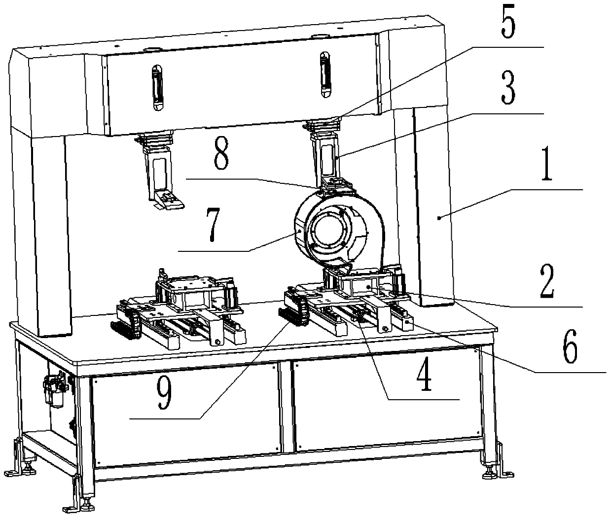
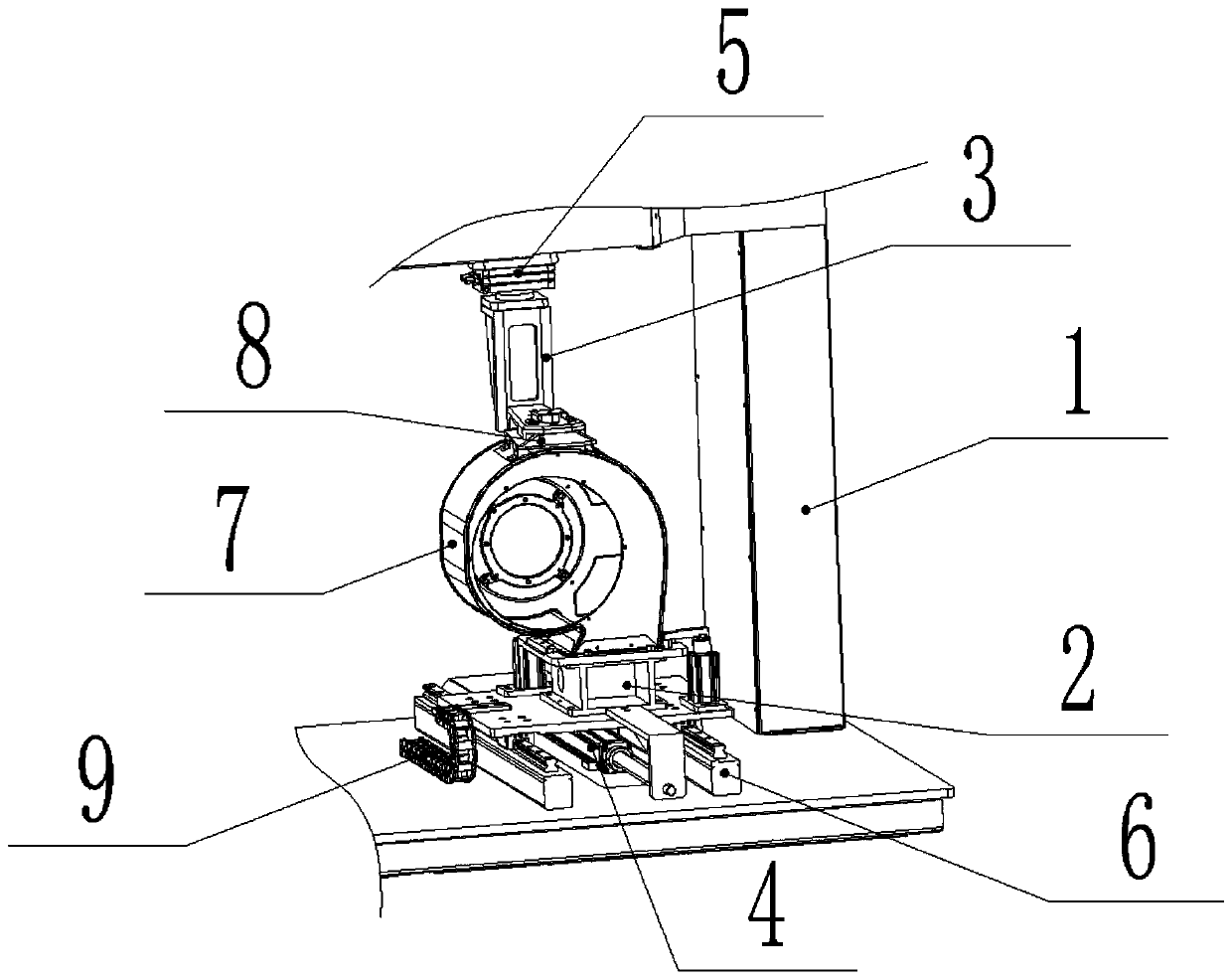
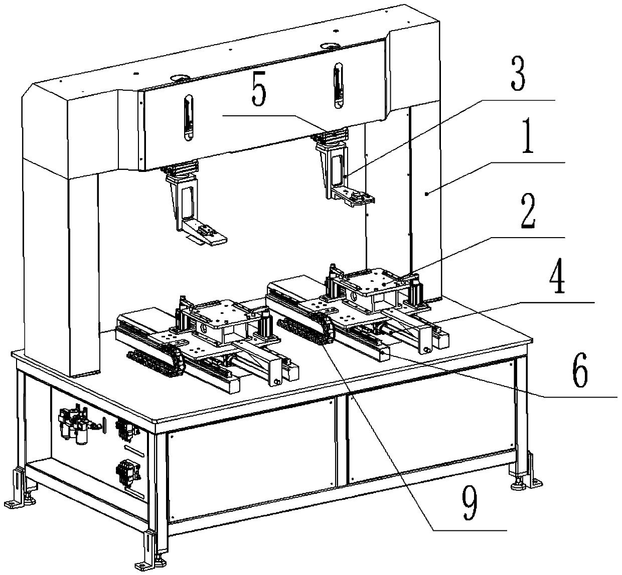
[0038] Such as Figure 1-7 As shown, a volute oil guiding groove positioning device provided in this embodiment includes:

[0039] fuselage 1;

[0040] A positioning and clamping mechanism 2 for positioning and clamping the volute 7;

[0041] The first driving mechanism 4 is arranged on the body 1 and connected with the positioning clamping mechanism 2, and is used to drive the positioning clamping mechanism 2 to move linearly;

[0042] A clamp mechanism 3 for positioning and clamping the oil guide groove 8;

[0043] The second driving mechanism 5 is arranged on the body 1 and connected with the clamp mechanism 3 for driving the clamp mechanism 3 to move linearly.

[0044] When riveting in this embodiment, the positioning and clamping mechanism 2 realizes the positioning and clamping of the volute 4, and the clamp mechanism 3 realizes the positioning and clamping of the oil guide groove 8, which is stable and reliable, and improves the riveting efficiency and riveting of th...

Embodiment 2

[0060] Such as Figure 1-8 As shown, a volute oil guide groove riveting system provided in this embodiment includes the volute oil guide groove positioning device described in Embodiment 1, and also includes a riveting and retrieving device. The riveting and retrieving device includes a robot 10 and the The riveting pliers and the retrieving clip connected with the robot 10, wherein the riveting pliers and the retrieving clip are integrated into an integrated structure, corresponding to Figure 8 The reference numeral 11 in the figure, and the robot 10 is installed on the ground through the base 12, and the robot 10 adopts the IRB6700 robot of Shanghai ABB Engineering Co., Ltd. During riveting, the volute oil guide groove positioning device realizes the positioning and clamping of the volute 7 and the guide groove 8, and the riveting pliers are controlled by the robot 10 to complete the riveting of the volute 7 and the guide groove 8; The finished product is removed, so that ...


PUM


Abstract

The invention discloses a positioning device for a spiral case oil guide groove. The positioning device for the spiral case oil guide groove comprises a machine body, a positioning and clamping mechanism, a first driving mechanism, a clamp mechanism, and a second driving mechanism; the positioning and clamping mechanism is used for positioning and clamping the spiral case; the first driving mechanism is arranged on the machine body and is connected with the positioning clamping mechanism, and is used for driving the positioning and clamping mechanism to move linearly; the clamp mechanism is used for positioning and clamping the oil guide groove; and the second driving mechanism is arranged on the machine body and connected with the clamp mechanism, and is used for driving the clamp mechanism to move linearly. The invention also provides a riveting system for the spiral case oil guide groove. The riveting system for the spiral case oil guide groove comprises the spiral case oil guide groove positioning device and a riveting material taking device. According to the positioning device for the spiral case oil guide groove and the riveting system, the automation degree is high, the labor intensity is low, the production efficiency is high, and the riveting quality is high.

Description

technical field [0001] The invention relates to the technical field of riveting equipment, in particular to a volute oil guiding groove positioning device and a riveting system. Background technique [0002] TOX riveting technology is a rivetless riveting technology, which can complete the connection of two or more layers of plates of the same or different materials, and the thickness of the plates can be the same or different. Under the same conditions, the static connection strength of TOX single point is 50%-70% of spot welding, and the double point is the same as spot welding. [0003] Oil and water will accumulate in the volute of the range hood during use. In order not to affect normal use and facilitate cleaning, the oil and water need to be discharged. Therefore, there are oil drain holes and oil guide grooves at the bottom of the volute; The oil groove is generally welded or riveted on the volute. When the existing oil guide groove and the volute are riveted, ther...

Claims


Application Information

Patent Timeline
Patent Type & Authority Applications(China)
IPC IPC(8): B23P19/00B23P19/02B23P19/027
CPCB23P19/00B23P19/02B23P19/027
Inventor 张人斌
Owner 湖南创研智能装备有限公司
Why Eureka
Try Eureka