
A rail vehicle corbel, underframe and underframe welding method

A technology for rail vehicles and corbels, which is applied to the underframe, welding equipment, welding equipment, etc., and can solve the problems of long working hours, costs, welding deformation, etc.

Active Publication Date: 2021-07-16
ZHUZHOU ELECTRIC LOCOMOTIVE CO LTD
View PDF9 Cites 0 Cited by
  • Summary
  • Abstract
  • Description
  • Claims
  • Application Information

AI Technical Summary

Problems solved by technology

With the full-length floor structure, the welds between the corbel beam and the underframe floor are concentrated on one side, which is easy to cause welding deformation
In addition, the process gap is usually set on the lower plane of the corbel. After the cover plate and the corbel are welded, the underframe of the car body needs to be machined as a whole because of the need to smooth the weld seams concentrated on the lower plane, which occupies a large area of ​​the underframe. The working hours of large stations are long and cost more manpower

Method used


Image

  • A rail vehicle corbel, underframe and underframe welding method
  • A rail vehicle corbel, underframe and underframe welding method
  • A rail vehicle corbel, underframe and underframe welding method

Examples


Embodiment 1

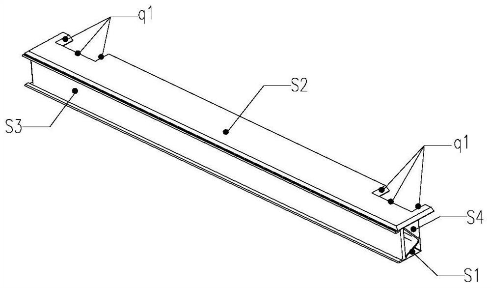
[0063] The present invention discloses a rail vehicle bolster, wherein the rail vehicle bolster comprises a bolster main body, an end cover plate 302 and a floor connecting profile 307 .

[0064] The floor connecting profiles 307 are respectively welded on the longitudinal sides of the corbel main body, and the outer side of the floor connecting profiles 307 are welded with the short floor 305 and the long floor 306 of the underframe respectively. The framed floor adopts a non-through-length floor structure, that is, the floor is disconnected at the rail vehicle bolster.

[0065] That is, the floor connecting profile is welded inward to the main body of the corbel, and outwardly welded to the underframe floor. Connect them in the order of underframe floor, floor connecting profile, and corbel main body.

[0066] The transverse ends of the top surface of the corbel main body are provided with technological gaps, and the end cover plates are blocked on the technological gaps. ...

Embodiment 2

[0072] In the second embodiment provided by the present invention, the structure of the rail vehicle bolster in this embodiment is similar to that of the rail vehicle bolster in the first embodiment, the similarities will not be repeated, and only the differences will be described.

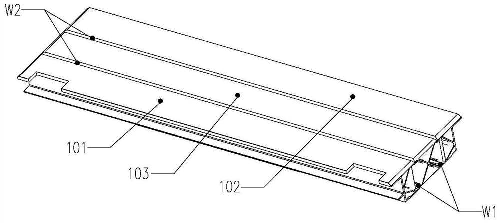
[0073] In this embodiment, the present invention discloses that the main body of the bolster includes a first side bolster 101, a second side bolster 102 and a middle bolster 103, and the first side bolster 101 and the second side bolster 102 are welded in the middle respectively. Longitudinal sides of corbel 103 .

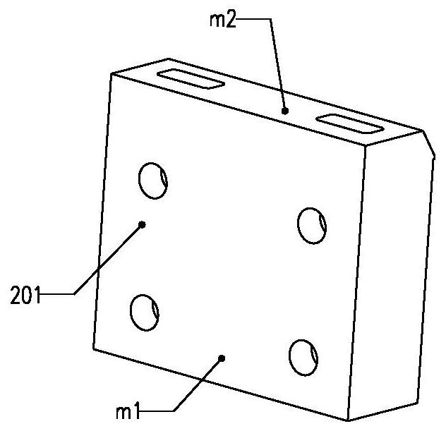
[0074] Further, the present invention discloses that the rail vehicle bolster further includes an anti-rolling structure 104 , and the anti-rolling structure 104 includes an anti-rolling mounting seat 201 and a positioning screw block 202 .

[0075] The bottom surface of the first side bolster 101 is provided with a mounting notch, the anti-rolling mounting seat 201 is welded in the m...

Embodiment 3

[0095] The present invention provides an underframe comprising a rail vehicle bolster as in any of the above embodiments.

[0096] Since the underframe disclosed in the present invention includes the rail vehicle bolster in any of the above embodiments, the beneficial effects of the above-mentioned rail vehicle bolster are all included in the underframe disclosed in the present invention.


PUM


Abstract

The invention discloses a rail vehicle bolster, a bottom frame and a welding method for the bottom frame. The rail vehicle bolster comprises a bolster main body, an end cover plate and floor connecting profiles welded on the longitudinal sides of the bolster body; the longitudinal direction of the bolster body is The outer sides of the floor connecting profiles at both ends are welded to the floor respectively, and the top surface of the corbel main body is flush with the top surface of the floor; there are process gaps on both sides of the top surface of the corbel main body; the inner rib plate of the corbel main body and the inner side of the bottom frame side beam Through the vertical welding seam welding therebetween, the end cover plate is covered with a process gap, and the periphery of the end cover plate is welded with the main body of the corbel, and the top surface of the main body of the corbel and the side beam of the chassis are welded by the longitudinal weld therebetween. The corbel outer rib plate of the corbel main body and the underframe side beam are welded through the vertical welding seam therebetween, and the bottom surface of the corbel main body and the underframe side beam are welded through the longitudinal welding seam therebetween. The technological gap is opened on the top surface of the main body of the corbel, and the floor is arranged in blocks, so that the welding seam between the corbel and the floor is prevented from being concentrated on one side, and the welding deformation is reduced.

Description

technical field [0001] The invention relates to the technical field of rail transit vehicle underframes, in particular to an aluminum composite material rail vehicle bolster, an underframe and a welding method for the underframe. Background technique [0002] The bolster is the main force-bearing component of the underframe structure of the vehicle body. It plays the role of connecting the bogie and transmitting the longitudinal compression force and traction force. It is the key structure for power transmission to realize the safe driving of the vehicle. [0003] At present, when the corbel is connected to the floor of the underframe, the upper plane of the corbel is directly contacted and installed with the lower surface of the full-length floor. The connection between the bolster and the side beam of the chassis is realized by the vertical welding seam of the inner plane of the bolster and the side beam of the underframe, and the welding seam connected in the longitudinal...

Claims


Application Information

Patent Timeline
Patent Type & Authority Patents(China)
IPC IPC(8): B61F1/08B23K31/02B23K37/047
CPCB23K31/02B23K37/047B61F1/08
Inventor 李丽苏柯刘永强钟磊王国军张长庚
Owner ZHUZHOU ELECTRIC LOCOMOTIVE CO LTD
Learn More