
Fine splitting machine for aluminum foil

A fine separation and cutting machine technology, applied in the direction of winding strips, sending objects, thin material processing, etc., can solve the problems of increased loss of aluminum foil coils and equipment, affecting production efficiency, and inaccurate dimensions of aluminum foil, etc., to prevent Off-winding and unwinding, improving production efficiency, and the effect of precise aluminum foil size

Pending Publication Date: 2019-12-20
ZHUOZHOU HAOYUAN FOIL IND +1
View PDF0 Cites 3 Cited by
  • Summary
  • Abstract
  • Description
  • Claims
  • Application Information

AI Technical Summary

Problems solved by technology

[0002] The aluminum foil slitting machine is mainly used to cut the aluminum foil coil with a larger width into smaller aluminum foil coils according to the requirements, and the current aluminum foil slitting machine, when cutting the aluminum foil, the aluminum foil will be in the traction conduction Sliding and deflection often occur during the process, and the deflected aluminum foil becomes waste after being cut, which will cause unnecessary increase in the loss of aluminum foil coils and equipment. Therefore, it is currently necessary for workers to monitor whether the aluminum foil is being conveyed by the traction roller. If there is a deviation in the middle, it needs to be stopped for manual correction, which will cause a large error and seriously affect the production efficiency. Not only that, the sliding of the aluminum foil on the traction roller will make the transmission of the aluminum foil unstable. Moreover, the current winding rollers cannot guarantee the same winding tension, which leads to irregular cross sections of the finished winding products. Therefore, the current aluminum foil slitting machine has partial winding and unwinding, which makes the size of the aluminum foil inaccurate and seriously affects the quality of the aluminum foil. Productivity

Method used


Image

  • Fine splitting machine for aluminum foil
  • Fine splitting machine for aluminum foil
  • Fine splitting machine for aluminum foil

Examples


Embodiment Construction

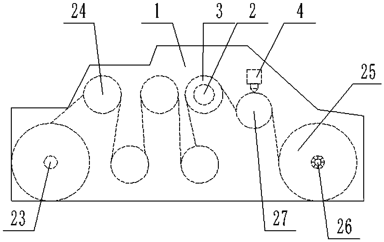
[0022] The following will clearly and completely describe the technical solutions in the embodiments of the present invention with reference to the accompanying drawings in the embodiments of the present invention. Obviously, the described embodiments are only some, not all, embodiments of the present invention. Based on the embodiments of the present invention, all other embodiments obtained by persons of ordinary skill in the art without making creative efforts belong to the protection scope of the present invention.

[0023] In order to make the above objects, features and advantages of the present invention more comprehensible, the present invention will be further described in detail below in conjunction with the accompanying drawings and specific embodiments.

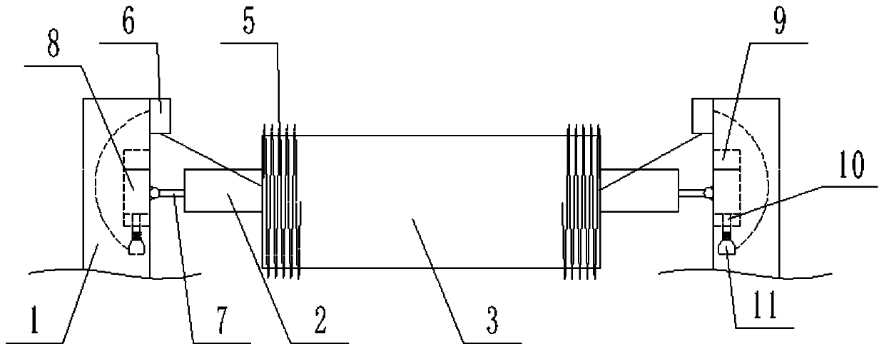
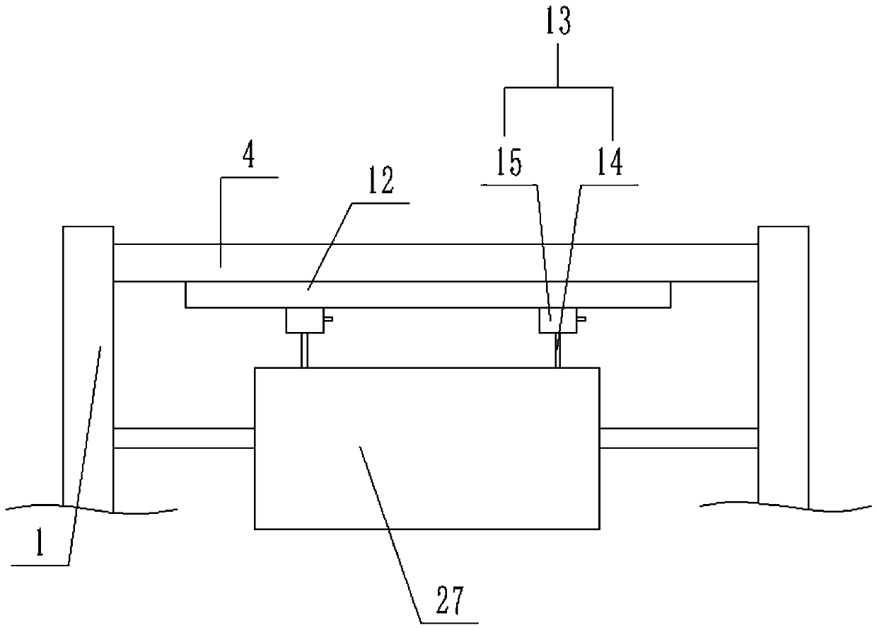
[0024] refer to Figure 1-6 , the present invention provides a fine aluminum foil slitting machine, comprising a frame 1, on which a discharge mechanism, a traction mechanism, and a winding machine hook are sequen...


PUM


Abstract

The invention discloses a fine splitting machine for an aluminum foil. The machine comprises a rack, wherein a discharging mechanism, a traction mechanism and a winding machine hook are sequentially coupled to the rack in a shaft coupling mode; an automatic deviation rectifying device is arranged between the traction mechanism and the winding mechanism and comprises a deviation rectifying shaft; adeviation rectifying roller sleeves the deviation rectifying shaft; detection devices are arranged at two ends of the deviation rectifying roller; adjusting parts are arranged at two ends of the deviation rectifying shaft; the detection devices are used for transmitting signals to the adjusting parts; a cutting mechanism is arranged between the automatic deviation rectifying device and the winding mechanism; the cutting mechanism comprises a cutter frame; two ends of the cutter frame are fixedly connected to the rack; the cutter frame is connected with a cutter device in a sliding mode; a cutting roller is arranged at the lower part of the cutter frame; two ends of the cutting roller are coupled to the rack in a shaft coupling mode; the winding mechanism comprises a winding roller; a sliding differential shaft is inserted into the winding roller; and two ends of the sliding differential shaft are shafted to the rack. The machine is capable of automatically rectifying and regularly coiling off-tracking coiled materials.

Description

technical field [0001] The invention relates to the field of aluminum foil processing equipment, in particular to an aluminum foil fine cutting machine. Background technique [0002] The aluminum foil slitting machine is mainly used to cut the aluminum foil coil with a larger width into smaller aluminum foil coils according to the requirements, and the current aluminum foil slitting machine, when cutting the aluminum foil, the aluminum foil will be in the traction conduction Sliding and deflection often occur during the process, and the deflected aluminum foil becomes waste after being cut, which will cause unnecessary increase in the loss of aluminum foil coils and equipment. Therefore, it is currently necessary for workers to monitor whether the aluminum foil is being conveyed by the traction roller. If there is a deviation in the middle, it needs to be stopped for manual correction, which will cause a large error and seriously affect the production efficiency. Not only th...

Claims


Application Information

Patent Timeline
Patent Type & Authority Applications(China)
IPC IPC(8): B65H23/038B65H18/10B65H35/02B65H23/195
CPCB65H23/038B65H18/10B65H35/02B65H23/1955B65H2701/1732
Inventor 张建杨讨论
Owner ZHUOZHOU HAOYUAN FOIL IND
Learn More