Supercharge Your Innovation With Domain-Expert AI Agents!

Spindle operation detecting system

A technology of running detection and spindle, which is applied in the field of spindle running detection system, can solve the problems of 0.5mm or even 1mm, affecting the direction of the spindle, economic loss, etc., to achieve accurate received information, simple structure, and prevent the direction of the spindle Effect

Pending Publication Date: 2019-12-20
TIANJIN HENGYUAN TRANSDUCERS TECH
View PDF0 Cites 0 Cited by
  • Summary
  • Abstract
  • Description
  • Claims
  • Application Information

AI Technical Summary

Problems solved by technology

However, during the movement of the spindle, if the movement is not stable, there will be a push-pull force between the chain links, and there will be a certain moment when the gap becomes larger to 0.5mm or even 1mm, and the optical path passes through the gap, making the photoelectric The detection error of the monitor will affect the direction of the subsequent spindles, and even cause serious economic losses

Method used


Image

  • Spindle operation detecting system
  • Spindle operation detecting system
  • Spindle operation detecting system

Examples


Embodiment Construction

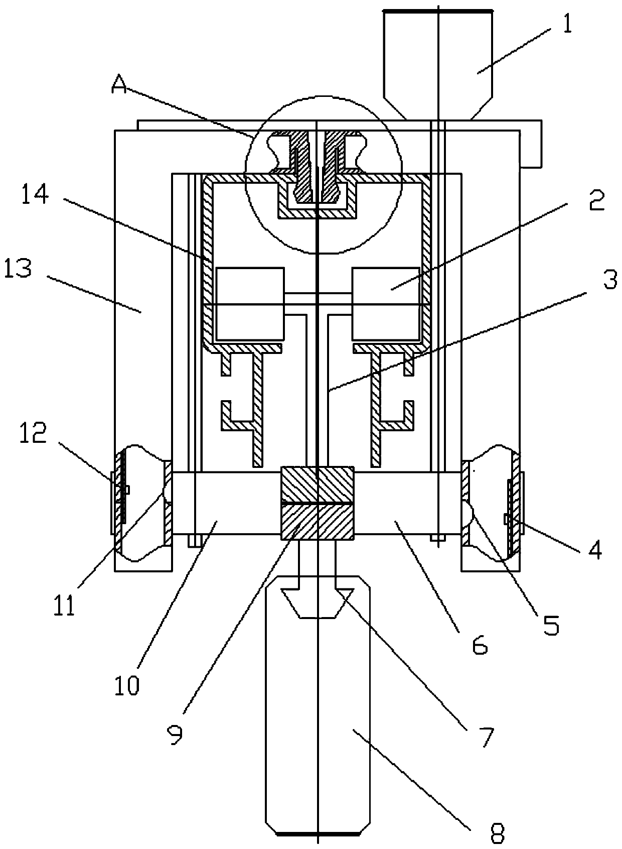
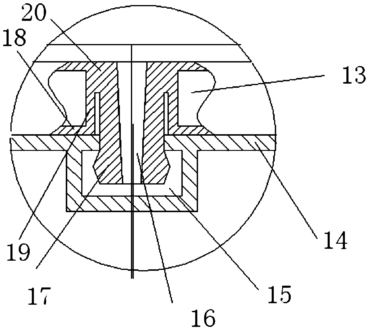
[0015] A spindle operation detection system, which includes a spindle transmission track 14, a plurality of spindle installation frames 3 with rollers 2, a spindle 8, a drive chain 9 and multiple sets of photoelectric detection devices, the rollers of the spindle installation frame are clamped on the spindle transmission rail Above, a yarn hook 7 is provided below the spindle installation frame, and the spindles are hung on the yarn hook. The fixed frame 13, the photoelectric transmitter 12 and the photoelectric receiver 4, the fixed frame is a door-shaped structure, which includes a top frame and two side frames, a motor 1 is fixedly installed on the spindle transmission track, and the motor shaft drives the driving sprocket 6 rotation, a driven sprocket 10 is installed next to the driving sprocket, and the drive chain is located between the driving sprocket and the driven sprocket and is driven by the driving sprocket to move along the extension direction of the spindle trans...


PUM


Abstract

The invention relates to the technical field of textile equipment, in particular to a spindle operation detecting system. The spindle operation detecting system comprises a spindle conveying rail, spindle installing frames, spindles, a driving chain and a plurality of photoelectric detecting devices. Wheels of the spindle installing frames are clamped on the spindle conveying rail. The spindles are hung on yarn hooks of the spindle installing frames. The lower portions of the spindle installing frames are hung on the driving chain. A motor is fixedly installed on the spindle conveying rail. Arotating shaft of the motor drives a driving chain wheel to rotate. The driving chain is located between the driving chain wheel and a driven chain wheel. Two side frames of a fixing frame are each provided with a lens hole. A photoelectric emitter lens is located in the photoelectric emitter lens hole. A photoelectric receiver lens is located in the photoelectric receiver lens hole. Chain sections are located on the connecting line between the photoelectric emitter lens hole and the photoelectric receiver lens hole. The spindle operation detecting system is simple in structure, convenient toinstable, stable in transmission and free of detection failures.

Description

technical field [0001] The invention relates to the technical field of textile equipment, in particular to a spindle operation detection system. Background technique [0002] Under the background of Big Times Intelligence+, a track line for transporting spindles has appeared in the cotton spinning industry, which aims to reduce the time and cost of manual handling and make the transport more smooth and controllable. At present, the spindle and the track are not in direct contact, but are realized through a connecting rod between the spindle and the track. The connecting rod is put into the track, and there is a yarn hook for hanging the spindle under the connecting rod. In order to facilitate the turning movement of the connecting rod in the track, the connecting rod is usually connected by multiple cuboid chain links with a cross-section of 20mmx20mm and a short length. The motor above the track drives the chain link by controlling the rotation of the motor drive wheel in c...

Claims


Application Information

Patent Timeline
IPC IPC(8): D01H13/32
CPCD01H13/32
Inventor 贺智勇
Owner TIANJIN HENGYUAN TRANSDUCERS TECH
Features
  • R&D
  • Intellectual Property
  • Life Sciences
  • Materials
  • Tech Scout
  • Unparalleled Data Quality
  • Higher Quality Content
  • 60% Fewer Hallucinations
Learn More