Cooling type water permeable brick for sponge city

A technology of sponge city and permeable bricks, which is applied to pavements, roads, and pavement details paved with prefabricated blocks. It can solve the problems of poor water storage and cooling effects, and achieve the goals of improving utilization, expanding area, and speeding up drainage. Effect

Active Publication Date: 2019-12-20
HENAN UNIV OF URBAN CONSTR
View PDF4 Cites 16 Cited by
  • Summary
  • Abstract
  • Description
  • Claims
  • Application Information

AI Technical Summary

Problems solved by technology

[0005] The purpose of the present invention is to solve the above problems of poor water storage and cooling e

Method used


Image

  • Cooling type water permeable brick for sponge city
  • Cooling type water permeable brick for sponge city
  • Cooling type water permeable brick for sponge city

Examples


Embodiment 1

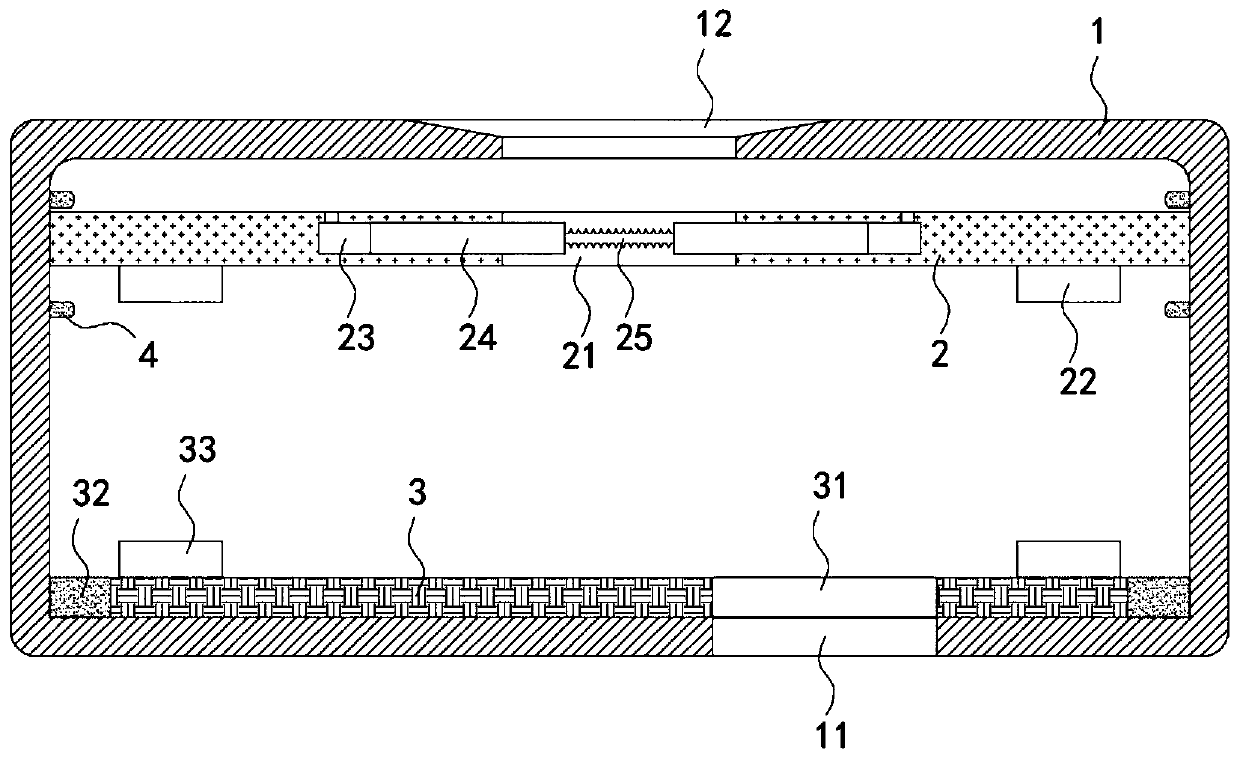
[0026] like figure 1 As shown, a cooling type water permeable brick for sponge city includes a brick body 1, and the inside of the brick body 1 is provided with a cavity. The bottom opening is arranged and communicated with the inside of the brick body 1, so that the rainwater on the road surface can be collected quickly and flow into the brick body 1, thereby speeding up the drainage speed of the road surface and the infiltration of rainwater.

[0027] In this embodiment, the lower surface of the brick body 1 is provided with permeable holes 11, and the inner wall of the brick body 1 is slidably connected with a lifting plate 2. The density of the lifting plate 2 is smaller than that of water. It should be noted that the inner wall of the brick body 1 The upper part is fixedly connected with two limit rings 4 for limiting the lifting plate 2, which can limit the lifting plate 2, the lifting plate 2 is provided with a through hole 21, and the inner bottom surface of the brick ...

Embodiment 2

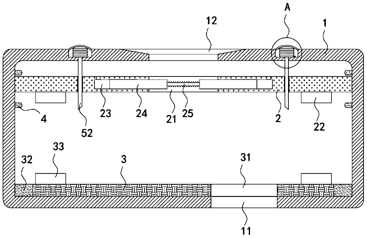
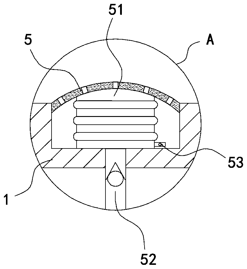
[0033] like Figure 2-4 As shown, the difference between this embodiment and Embodiment 1 is that the upper surface of the brick body 1 is provided with a groove, and the side wall of the groove is fixedly connected with an arc-shaped and upwardly arched flexible pedal 5. It is illustrated that a plurality of flexible pedals 5 are arranged in an annular array on the upper surface of the brick body 1. The flexible pedals 5 are porous and the surface is provided with anti-slip protrusions, which play a good anti-skid effect and prevent pedestrians from walking on rainy days due to the brick surface. Smooth and fall, the lower surface of the flexible pedal 5 is fixedly connected with the bottom surface of the groove through the airbag 51, the lower end of the airbag 51 is fixedly connected with a one-way blowing pipe 52, and the one-way blowing pipe 52 only allows the gas in the airbag 51 to blow to the brick. Inside the body 1, the lower end of the one-way blowing pipe 52 runs t...


PUM


Abstract

The invention belongs to the field of sponge city construction, and particularly relates to a cooling type water permeable brick for a sponge city. The cooling type water permeable brick for the sponge city comprises a brick body; the interior of the brick body is provided with a cavity; a water permeable hole is formed in the lower surface of the brick body; the inside wall of the brick body is in sliding connection with a lifting plate; the density of the lifting plate is less than that of water; a through hole is formed in the lifting plate; the inner bottom surface of the brick body is rotatably connected with a water seepage plate; the water seepage plate is internall provided with a water seepage hole which corresponds to the position of the water permeable hole and communicates withthe water permeable hole; the side wall of the water seepage plate is fixedly with the inside wall of the brick body through a coil spring; the lower surface of the lifting plate is fixedly connectedwith two permanent magnetic blocks. According to the cooling type water permeable brick for the sponge city, the water storage and water seepage states can be regulated automatically according to rainfall capacity; the utilization rate of rainwater is improved; a good sponge effect is achieved; the evaporating speed of the rainwater in the brick body can be regulated according to the temperatureof a city; a good cooling effect is achieved; and moreover, the cooling speed is higher for the road surface with large population flow in the city.

Description

technical field [0001] The invention belongs to the field of sponge city construction, and in particular relates to a cooling type permeable brick for sponge city. Background technique [0002] Building a sponge city, that is, building a low-impact development rainwater system, mainly refers to the realization of a benign hydrological cycle in the city through various technical approaches such as "seepage, stagnation, storage, purification, use, and drainage", and improves the infiltration, regulation and storage of runoff rainwater. , purification, utilization and discharge capacity, maintain or restore the sponge function of the city, in the construction of the sponge city, and in the process of infiltration, storage, purification, utilization and discharge of rainwater, the cooling permeable brick plays a decisive and important role. [0003] Traditional cooling permeable bricks for sponge cities are mostly equipped with independent water storage tanks and permeable holes...

Claims


Application Information

Patent Timeline
IPC IPC(8): E01C5/04E01C11/00E01C11/22E01C11/24
CPCE01C5/04E01C11/00E01C11/225E01C11/24
Inventor 万祥云吴丽田俊峰赵瑞锋顾效纲崔弼峰
Owner HENAN UNIV OF URBAN CONSTR
Why Eureka
Try Eureka