Coal bed gas mining coal powder discharge device

A coalbed methane and pulverized coal technology, which is applied in the field of pulverized coal discharge device in coalbed methane mining, can solve the problems of pump leakage, slow operation, precipitation, etc.

Active Publication Date: 2021-04-09
CHINA UNIV OF MINING & TECH (BEIJING)
View PDF5 Cites 0 Cited by
  • Summary
  • Abstract
  • Description
  • Claims
  • Application Information

AI Technical Summary

Problems solved by technology

[0002] During the exploitation of coalbed methane, if the quality of water discharged from the drainage well gradually turns black, it may indicate that the pulverized coal may be clogged or pulverized coal may have precipitated. In this case, if the coal powder settles in the pump barrel, it is easy to get stuck softly, resulting in a decrease in liquid discharge, unloading phenomenon in the down stroke, and severe shaking of the stroke hanger; , During the operation of the pumping unit, the downstroke current is small and the operation is fast, and the upstroke current is large and the operation is slow. The power diagram shows that the maximum load is larger than the normal value; if the coal powder is deposited on the valve seat, the pump will be lost. , resulting in reduced liquid output and low pump efficiency, the leakage power diagram of the fixed valve shows that the lower left corner and the lower right corner are missing, the unloading of the down stroke is delayed, and the load is advanced in the up stroke
Therefore, in the process of mining coalbed methane, it is necessary to discharge the pulverized coal while ensuring the reliability of the discharge. The current discharge only relies on the way of pumping water. This method of pulverized coal is easy to cause precipitation and affects the discharge. Effect

Method used


Image

  • Coal bed gas mining coal powder discharge device
  • Coal bed gas mining coal powder discharge device

Examples


Embodiment Construction

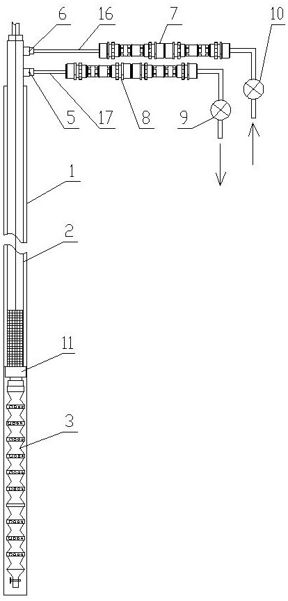
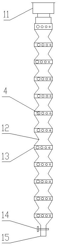
[0018] Such as figure 1 and figure 2 As shown, a pulverized coal discharge device for coalbed methane mining of the present invention includes a pulverized coal anti-settling device 3, a liquid injection assembly and a liquid discharge assembly, and the pulverized coal anti-settling device 3 is located in the shaft of a coalbed methane extraction well 1. The liquid injection assembly and the liquid discharge assembly are located outside the upper well of the coalbed methane extraction well 1. The pulverized coal anti-settling device 3 is connected to the lower end of the extraction rod 2 coaxially. The upper part is connected, the liquid injection component can inject the anti-settling agent liquid into the pulverized coal anti-settling device 3 through the extraction rod 2 in the form of pulse pressure, and the liquid drainage component can discharge the anti-settling agent 3 through the extraction rod 2 The sinking liquid is discharged.

[0019] The pulverized coal anti-s...


PUM


Abstract

The invention discloses a pulverized coal discharge device for coalbed methane mining. A liquid injection component and a liquid discharge component are used to inject an anti-settling agent liquid downhole. It dissolves very well and ensures discharge at the same time, while the liquid injection component injects the anti-settling agent liquid into the pulverized coal anti-settling device in the form of pulse pressure, and the liquid discharge component discharges the anti-settling agent liquid discharged from the pulverized coal anti-settling device, and the slurry will flow from the coal The liquid outlet holes on the powder anti-sedimentation device are discharged to realize the dissolution and flushing of coal powder. At the same time, because the diameters of each group of liquid outlet holes are different, the flow rate and flow rate of the liquid flowing out of the liquid outlet holes are different, which can help the liquid Flow occurs in the downhole, which helps to realize the discharge of coal powder; the present invention adopts a plurality of injection discs and liquid injection capsules, which can be stretched and adjusted under the pulse pressure, and the liquid flow rate out of the liquid outlet hole is different, The pressure will be different due to the deformation, which will make the liquid wash away the pulverized coal and ensure the discharge effect.

Description

technical field [0001] The invention belongs to the technical field of similar material testing, and in particular relates to a pulverized coal discharge device for coalbed methane mining. Background technique [0002] During the exploitation of coalbed methane, if the quality of water discharged from the drainage well gradually turns black, it may indicate that the pulverized coal may be clogged or pulverized coal may have precipitated. In this case, if the coal powder settles in the pump barrel, it is easy to get stuck softly, resulting in a decrease in liquid discharge, unloading phenomenon in the down stroke, and severe shaking of the stroke hanger; , During the operation of the pumping unit, the downstroke current is small and the operation is fast, and the upstroke current is large and the operation is slow. The power diagram shows that the maximum load is larger than the normal value; if the coal powder is deposited on the valve seat, the pump will be lost. , resulti...

Claims


Application Information

Patent Timeline
Patent Type & Authority Patents(China)
IPC IPC(8): E21B21/00E21B41/00
CPCE21B21/00E21B41/0078
Inventor 李勇麻振涛许卫凯
Owner CHINA UNIV OF MINING & TECH (BEIJING)
Why Eureka
Try Eureka