Pump body structure of constant-temperature and high-efficiency roots pump
A high-efficiency, constant temperature technology, applied in the components of pumping devices for elastic fluids, rotary piston/oscillating piston pump components, pumps, etc., can solve the problem of poor heat transfer effect, condensation of liquid or dust accumulation, Burns and other problems, to achieve the effect of improving heat exchange effect, realizing cooling effect and strengthening strength
- Summary
- Abstract
- Description
- Claims
- Application Information
AI Technical Summary
Problems solved by technology
Method used
Image
Examples
Embodiment 1
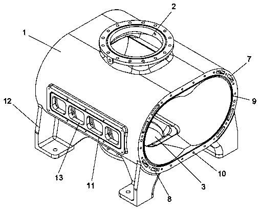
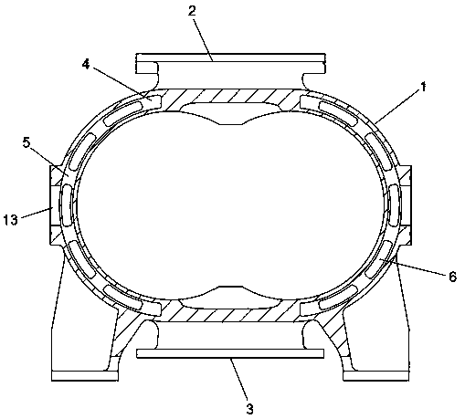
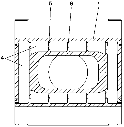
[0026] Embodiment one, such as Figure 1-5 As shown, a pump body structure of a constant temperature and high-efficiency Roots pump, the upper end of the pump casing 1 is provided with an air inlet 2, the lower end of the pump casing 1 is provided with an exhaust port 3, the inner cavity of the pump casing 1 is installed with a Roots rotor, and the pump casing 1 There is a jacket layer 4 inside the casing, and a number of reinforcing ribs 5 are fixedly installed in the jacket layer 4, and an oval through hole 6 for circulation is opened on the side of each reinforcing rib 5; A number of liquid outlets 7 and liquid inlets 8 are opened, and the liquid outlets 7 and liquid inlets 8 are all connected to the jacket layer 4; the jacket layer 4 is not only covered on both sides of the pump casing 1, but also on the Around the intake port 2 and the exhaust port 3.
[0027] When in use, the cooling water enters the jacket layer 4 through the liquid inlet 8 on the end face of the pump ...
Embodiment 2
[0030] Embodiment 2, based on a further improvement of Embodiment 1, at least one casting hole 13 is opened on both sides of the pump casing 1 , and each casting hole 13 is located between two reinforcing ribs 5 . The outer surface of the casting hole 13 is provided with a first sealing groove 9, and a first O-shaped sealing ring is installed in the first sealing groove 9, and the outer surface of the casting hole 13 is fixed with a jacket water layer panel by screws. By placing each casting hole 13 just between the two reinforcing ribs 5, it is ensured that the casting holes 13 will not affect the strength of the pump casing 1 and the jacket layer 4, and there is more space for casting Convenience; then seal the surface of the casting hole 13 by installing the jacket water layer panel and the first O-shaped sealing ring, so that a sealed cavity is formed in the jacket layer 4 .
Embodiment 3
[0031] Embodiment 3, based on the further improvement of Embodiment 1, the end face of the pump casing 1 corresponding to the liquid outlet 7 and the liquid inlet 8 is uniformly provided with several bolt holes 10, and the bolt holes 10 are connected with the liquid outlet 7 and the liquid inlet 8. Phase staggered. The inner chamber of the pump casing 1 is provided with a second sealing groove 11 along the circumference of the outer end surface, and a second O-ring is installed in the second sealing groove 11 . Therefore, during actual operation, the cooling liquid can enter or flow out of the jacket layer 4 of the pump casing 1 from the end cover adjacent to the pump casing 1, without resetting the liquid inlet or liquid outlet on the surface of the pump casing 1; and By installing a second O-ring seal between the inner cavity of the pump casing 1 and the liquid inlet 8 and the liquid outlet 7 of the jacket layer 4 , the coolant can be effectively prevented from penetrating i...
PUM
 Abstract
Description
Claims
Application Information
 - R&D
- Intellectual Property
- Life Sciences
- Materials
- Tech Scout
- Unparalleled Data Quality
- Higher Quality Content
- 60% Fewer Hallucinations
Browse by: Latest US Patents, China's latest patents, Technical Efficacy Thesaurus, Application Domain, Technology Topic, Popular Technical Reports.
© 2025 PatSnap. All rights reserved.Legal|Privacy policy|Modern Slavery Act Transparency Statement|Sitemap|About US| Contact US: help@patsnap.com


