
Method for measuring relationship between adhesion coefficient and slip rate under brake of railway vehicle and test bench

An adhesion coefficient, railway vehicle technology, applied in the field of railway vehicle adhesion characteristics testing, can solve problems such as difficulty, long line test time, inability to meet, etc., to reduce the test risk, improve the anti-skid exhaust structure, and reduce the power demand of the motor. Effect

Pending Publication Date: 2019-12-20
TONGJI UNIV
View PDF0 Cites 2 Cited by
  • Summary
  • Abstract
  • Description
  • Claims
  • Application Information

AI Technical Summary

Problems solved by technology

However, since the test was carried out at a low speed below 120km / h, it could no longer meet the high-speed operation needs of high-speed railways in my country (over 200km / h for existing lines and over 250km / h for new lines).
[0004] Due to the long time-consuming, high cost and difficulty of the line test, the current research is concentrated on the laboratory scale test, which has the advantages of simple implementation and low cost, but the non-linearity in the wheel-rail relationship makes it impossible to directly use the similar relationship from the scale test. Accurately reflect the real adhesion characteristics of the train in the test bench measurement results
At the same time, although there are some studies on adhesion characteristics based on full-scale test benches, they are mainly designed for traction conditions and cannot fully reflect the adhesion characteristics of brakes.

Method used


Image

  • Method for measuring relationship between adhesion coefficient and slip rate under brake of railway vehicle and test bench
  • Method for measuring relationship between adhesion coefficient and slip rate under brake of railway vehicle and test bench
  • Method for measuring relationship between adhesion coefficient and slip rate under brake of railway vehicle and test bench

Examples


specific Embodiment

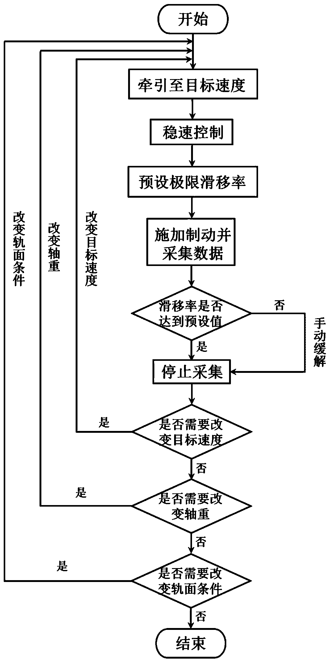
[0043] A test rig and method for measuring the relationship between the adhesion coefficient and the slip rate under the braking condition of a railway vehicle based on a rolling test rig. The specific implementation methods are as follows:

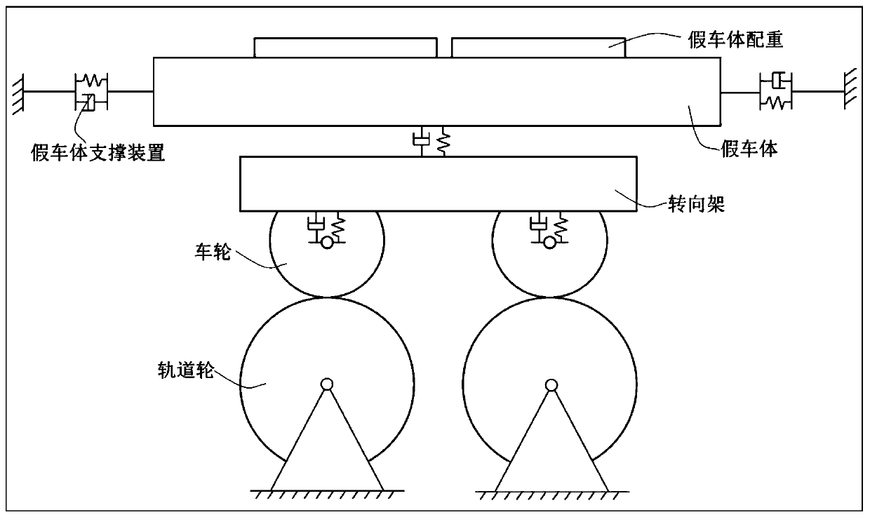
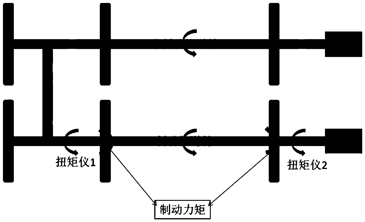
[0044] Rolling test bench for measuring such as figure 1 As shown, it includes rail wheels, bogies, dummy car bodies, dummy car body support devices, dummy car body counterweights, etc., including rail wheel traction motors not shown in the figure, and synchronous gears connecting two rail wheel pairs. Gearboxes, flywheels as inertial loads, and torque meters, encoders, speed sensors, and acquisition systems.

[0045] Preparation of measuring equipment includes:

[0046] Connect the two pairs of track wheels of the test bench with a synchronous gearbox so that they can rotate synchronously;

[0047] The moment of inertia of the mechanical flywheel set equipped on the test bench is configured to the maximum without considering the equiva...


PUM


Abstract

The invention relates to a method for measuring a relationship between an adhesion coefficient and a slip rate under brake of a railway vehicle and a test bench. The method comprises the following steps of firstly, confirming that all functions of the test bench are normal; after a target speed is pulled to be stabilized, switching a motor control mode to a torque control mode, and compensating control; presetting a slip rate limit value for a brake control device, installing an exhaust valve on a pipeline leading to a brake cylinder, after measurement is started, applying braking to a bogie,and collecting data in real time to compute the adhesion coefficient and the slip rate; when the slip rate reaches a preset value, rapidly emptying the pressure of the brake cylinder at one time through the exhaust valve; and repeating for many times for the same working condition, and eliminating a random error. The track wheel speed, axle weight and track surface conditions are changed sequentially, and the measurement is repeated. A three-dimensional curved surface is generated based on multiple groups of adhesion coefficient-slip rate relationship curves obtained by measurements at different speeds, and an adhesion coefficient extreme point connection line is depictured. Compared with the prior art, the method and the test bench have the advantages of low test requirements, low test risk and the like.

Description

technical field [0001] The invention relates to the testing of adhesion characteristics of railway vehicles, in particular to a method for measuring the relationship between adhesion coefficient and slip rate under the braking condition of railway vehicles based on a rolling test platform and a test platform. Background technique [0002] At present, the main braking method of railway vehicles is realized by the adhesion force transmitted between the wheels and rails. Wheel-rail adhesion is a key issue that restricts the safety and speed of high-speed railway operations. When the adhesion between the wheel and the rail is insufficient, it is very easy to slide or even lock, causing damage such as abrasion and peeling of the wheel tread and the rail. The abrasion of wheels and rails will become a random disturbance during the operation of the train, which will bring hidden dangers to the stability and smoothness of the train during operation. This external disturbance will re...

Claims


Application Information

Patent Timeline
IPC IPC(8): G01N19/04
CPCG01N19/04
Inventor 田春吴萌岭陈茂林马天和朱文良刘宇康
Owner TONGJI UNIV
Learn More