Square lens, light-emitting structure and lamp thereof

A light-emitting structure and lens technology, applied in the field of optical components, can solve the problems of energy waste, uneven crop growth, low yield, etc., and achieve the effect of convenient use

Pending Publication Date: 2019-12-20
杭州昌松光学有限公司
View PDF0 Cites 1 Cited by
  • Summary
  • Abstract
  • Description
  • Claims
  • Application Information

AI Technical Summary

Problems solved by technology

In recent years, due to the promotion of market demand, greenhouses are widely used to produce off-season flowers, fruits, vegetables, etc. Due to the short sunshine time in winter and spring, slow growth of crops, and low output, supplementary light is urgently needed; traditional supplementary light The lighting spot is generally circular, and the center is bright and the edge is dark, and the crops inside the greenhouse are arranged in a rectangle, which will lead to uneven illumination and uneven crop growth, and the mismatch between the lighting area and the crop planting area will lead to energy waste , which increases the cost; and the maximum capture of light energy and the full use of the potential of plant photosynthesis will be directly related to the benefits of agricultural production

Method used


Image

  • Square lens, light-emitting structure and lamp thereof
  • Square lens, light-emitting structure and lamp thereof
  • Square lens, light-emitting structure and lamp thereof

Examples


Embodiment Construction

[0059] The present invention will be described in detail below in conjunction with the accompanying drawings and specific embodiments, wherein the schematic embodiments and descriptions are only used to explain the present invention, but not as improper limitations to the present invention.

[0060] It should be noted that, in the case of no conflict, the embodiments in the present application and the features in the embodiments can be combined with each other. The present invention will be described in detail below with reference to the accompanying drawings and examples.

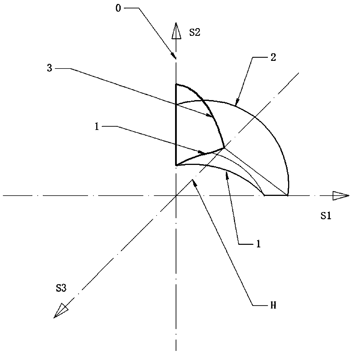
[0061] A square lens, including a first curve, a second curve, and a third curve; the expression of the first curve is: y 1 =a 10 ++a 11 x 1 +a 12 x 1 2 +a 13 x 1 3 ;in

[0062] The second curve expression is: y 2 =a 20 ++a 21 x 2 +a 22 x 2 2 +a 23 x 2 3 +a 24 x 2 4 +a 25 x 2 5 +a 26 x 2 6 ;in

[0063] a 20 = 25.42; a 21 = 1.046; a 22 =-0.4414; a 23 =0.07458;

[0064] a...


PUM


Abstract

The invention discloses a lens, which comprises a first curve, a second curve and a third curve, wherein an expression of the first curve is as follows: y1=a10++a11x1+a12x1<2>+a13x1<3>; an expressionof the second curve is as follows: y2=a20++a21x2+a22x2<2>+a23x2<3>+a24x2<4>+a25x2<5>+a26x2<6>; an expression of the third curve is as follows: y3=a30++a31x3+a32x3<2>+a33x3<3>+a34x3<4>; the first curve, the second curve and the third curve are all of a rotating array structure about a central axis; lofting is carried out by taking a first contour boundary line and a second contour line as contour boundary lines to obtain a first single body; the first single body is symmetrically overturned by taking H as an axis to obtain a second single body; the second single body takes the central shaft asa circle center annular array, the angle of the array is 90 degrees and a square lens body is obtained; the plane where the first curve is located is an incident plane, and the plane where the secondcurve and the third curve are located is an emergent plane; and the lens main body enables light rays to enter from the incident surface and exit from the emergent surface to form a square irradiationsurface. The square lens is used for supplementary lighting in the field of plant growth, so that a lighting region is matched with a crop planting region, and the benefit of agricultural productionis improved.

Description

technical field [0001] The invention relates to an optical element, in particular to a square lens, a light-emitting structure and a lamp. Background technique [0002] The lens is used to refract the light irradiated from one side to the other side, so as to realize the adjustment of the light irradiation and the adjustment of the irradiation range. The lighting tools used with the above lenses can be widely used in various industries; such as street lamps and lamps in the field of plant growth. [0003] As far as lights are used in the field of plant growth, plant lights are used in applications where there is no natural light or supplementary light is required. Because light is closely related to the growth of crops. In recent years, due to the promotion of market demand, greenhouses are widely used to produce off-season flowers, fruits, vegetables, etc. Due to the short sunshine time in winter and spring, slow growth of crops, and low output, supplementary light is urg...

Claims


Application Information

Patent Timeline
Patent Type & Authority Applications(China)
IPC IPC(8): G02B27/00F21V5/04F21V19/00F21Y105/16F21Y115/10
CPCF21V5/046F21V19/001F21Y2105/16F21Y2115/10G02B27/0012
Inventor 岑松原董田华赵亮
Owner 杭州昌松光学有限公司
Why Eureka
Try Eureka