Liftable central-positioned low-voltage switch cabinet

A low-voltage switchgear, center-mounted technology, applied in the field of liftable center-mounted low-voltage switchgear, can solve the problems of difficult maintenance of the switchgear, achieve the effect of convenient detection and maintenance, and improve stability

Inactive Publication Date: 2019-12-20
山东厚俞实业有限公司
View PDF5 Cites 11 Cited by
  • Summary
  • Abstract
  • Description
  • Claims
  • Application Information

AI Technical Summary

Problems solved by technology

[0004] The object of the present invention is to address the deficiencies of the prior art, to provide a liftable mid-mounted low-voltage switchgear, which includes a cabinet body, and the periphery of the cabinet is provided with a semi-enclosed external connection mechanism, and the semi-enclosed external connection mechanism The bottom end of the

Method used


Image

  • Liftable central-positioned low-voltage switch cabinet
  • Liftable central-positioned low-voltage switch cabinet
  • Liftable central-positioned low-voltage switch cabinet

Examples


Example Embodiment

[0020] Example 1

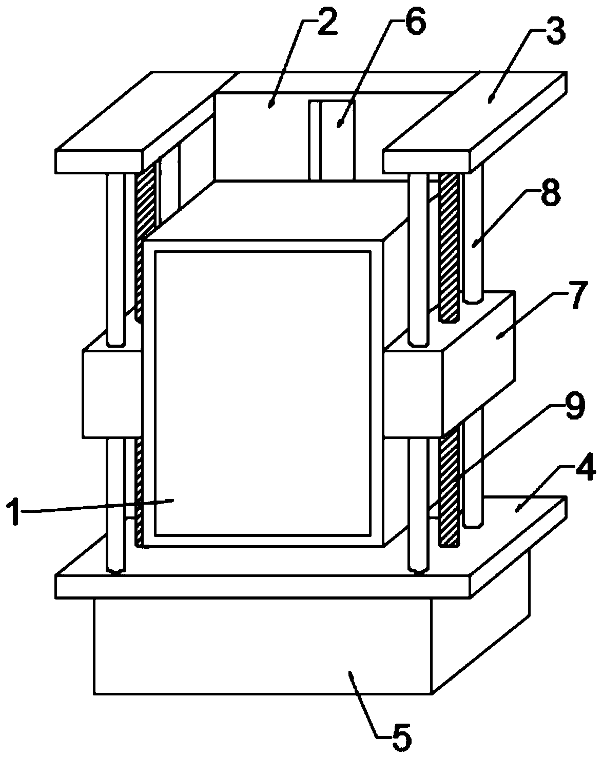
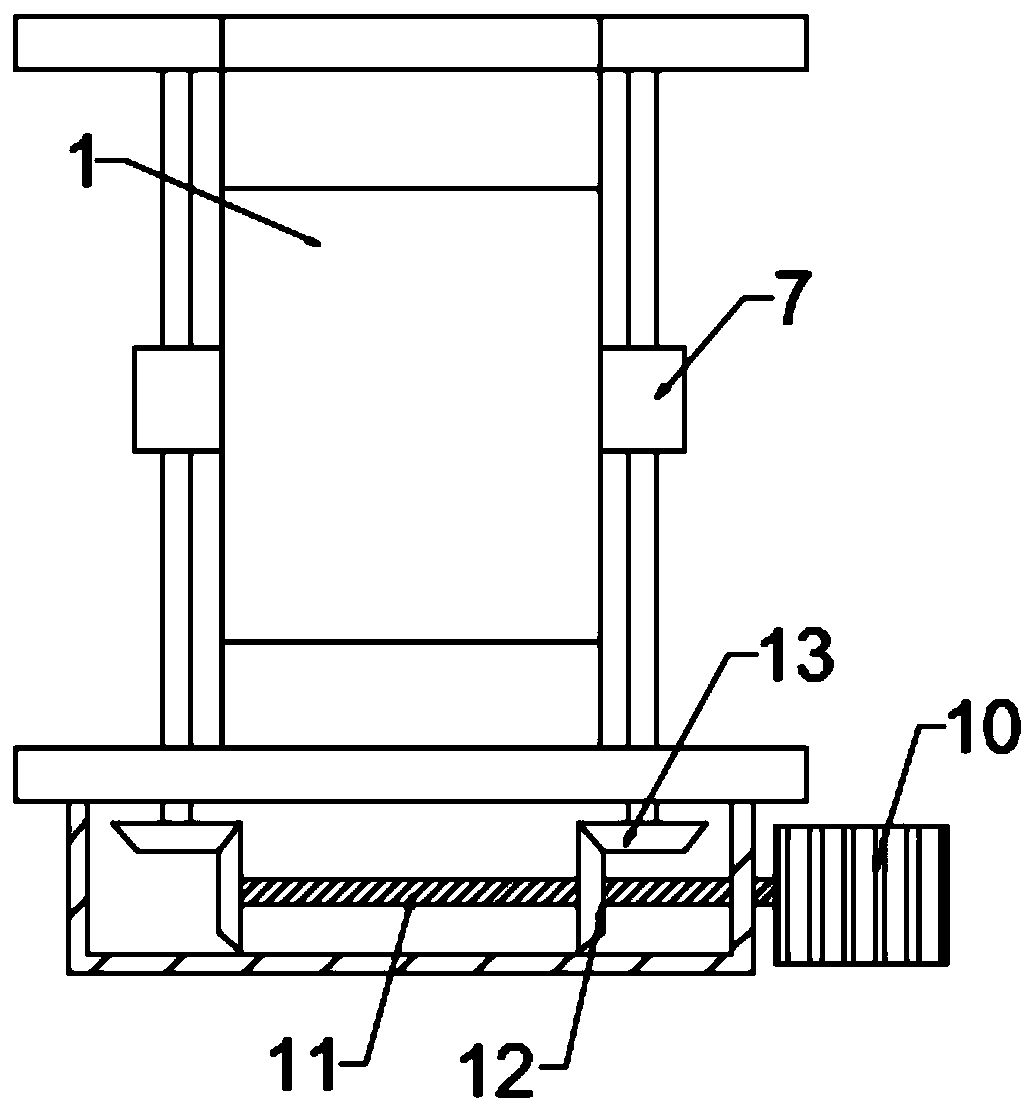
[0021] by Figure 1-3 As shown, a liftable mid-mounted low-voltage switchgear has a cabinet body 1. A semi-enclosed external mechanism is provided on the periphery of the cabinet body 1, and a motor box 5 is provided at the bottom end of the semi-enclosed external mechanism. A driving mechanism is provided inside the motor box 5, a lifting assembly is provided in the semi-enclosed external mechanism, and the lifting assembly is connected to the driving mechanism;

[0022] The cabinet 1 is an outer shell for a switch cabinet in the prior art, the cabinet 1 is slidably installed in the semi-enclosed external mechanism, and the cabinet 1 slides through a lifting assembly;

[0023] The semi-enclosed external mechanism includes a rear plate 2, a bottom plate 4 is fixed at the bottom end of the rear plate 2, a top plate 3 is fixed on both sides of the top end of the rear plate 2, and the lifting assembly is installed on the top plate 3 and Between the bottom plates 4; ...

Example Embodiment

[0028] Example 2

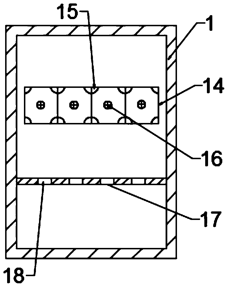
[0029] by image 3 As shown, a liftable mid-mounted low-voltage switch cabinet, cabinet body 1, the rear inner wall of the cabinet body 1 is provided with an instrument placement groove 14 in which three partitions 15 are evenly distributed There are four spaces, each with rubber pads 16 at the four corners, and screws 17 on the inner wall of each space;

[0030] The height and number of the instrument placement slot 14 and the number of partitions 15 can be increased or decreased according to actual conditions;

[0031] In this embodiment, the lower end of the meter placement slot 14 is further provided with a wire harness plate 18, and a wire harness hole 19 is opened in the wire harness plate 18;

[0032] The number of wire harness holes 19 is the same as the number of spaces separated by the partition 15;

[0033] The other structure in this embodiment is the same as that in the first embodiment.

[0034] In summary, the working principle of the present invention ...


PUM


Abstract

The invention discloses a liftable central-positioned low-voltage switch cabinet and relates to the technical field of a switch cabinet. The switch cabinet comprises a cabinet body, wherein a semi-enclosed external mechanism is arranged on the periphery of the cabinet body, a motor box is arranged at a bottom end of the semi-enclosed external mechanism, a driving mechanism is arranged in the motorbox, a lifting assembly is arranged in the semi-enclosed external mechanism, and the lifting assembly is connected with the driving mechanism. By starting a motor, the motor drives a first bevel gearto rotate through a rotating shaft, so a second bevel gear is driven to rotate, the cabinet body rises and falls under cooperation of a sliding block and a screw, moreover, a clamping block at a rearend of the cabinet body is matched with a sliding groove, so the cabinet body rising and falling stability is improved. Compared with the prior art, the switch cabinet is more flexible, and a workercan conveniently detect and maintain internal instruments and the like.

Description

Technical field [0001] The invention relates to the technical field of switch cabinets, in particular to a liftable middle-mounted low-voltage switch cabinet. Background technique [0002] Low-voltage switchgear is suitable for power plant, petroleum, chemical, metallurgical, textile and other industries. It is used for power transmission, distribution and power conversion. In order to ensure the normal use of low-voltage switchgear, it is necessary to regularly inspect and repair the internal components of the switchgear . [0003] However, most of the existing low-voltage switch cabinets are fixed and cannot be adjusted in height. It is very inconvenient for maintenance personnel to detect high and low electrical equipment during work. Therefore, we propose a liftable mid-mounted type low voltage switch box. Summary of the invention [0004] The purpose of the present invention is to provide a liftable mid-mounted low-voltage switchgear in view of the deficiencies of the prior a...

Claims


Application Information

Patent Timeline
IPC IPC(8): H02B1/30
CPCH02B1/303
Inventor 吴兵张侃侃胡晨光胡跃东武雅君苏陆琪
Owner 山东厚俞实业有限公司
Why Eureka
Try Eureka