LED driving circuit and dimming control method thereof

A LED drive and control method technology, applied in the field of power electronics, can solve problems such as load current asymmetry and AC voltage asymmetry

Pending Publication Date: 2019-12-20
HANGZHOU SILAN MICROELECTRONICS
View PDF0 Cites 4 Cited by
  • Summary
  • Abstract
  • Description
  • Claims
  • Application Information

AI Technical Summary

Problems solved by technology

The asymmetry of the AC voltage has nothing to do with the size of the conduction angle. The asym

Method used


Image

  • LED driving circuit and dimming control method thereof
  • LED driving circuit and dimming control method thereof
  • LED driving circuit and dimming control method thereof

Examples


Embodiment Construction

[0084] Various embodiments of the invention will be described in more detail below with reference to the accompanying drawings. In the various drawings, the same elements are denoted by the same or similar reference numerals. For the sake of clarity, various parts in the drawings have not been drawn to scale.

[0085] In this application, the term "conduction angle range" refers to the electrical angle range in which the thyristor in the dimmer conducts in the half power frequency cycle of the AC voltage under the user's dimming action, for example, in the positive half The range of the small conduction angle of the SCR in the cycle is 120° to 180°, and the range of the large conduction angle is 90° to 180°. The brightness of the LED lamp in the small conduction angle range is smaller than the brightness in the large conduction angle range.

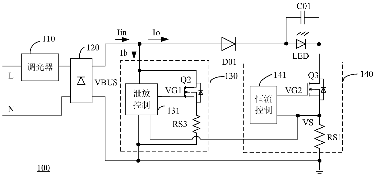
[0086] figure 1 A schematic circuit diagram of a thyristor dimming control system according to the prior art is shown. The thyristor...


PUM


Abstract

The invention discloses an LED driving circuit and a dimming control method thereof. The driving circuit is connected with a dimmer so as to acquire an AC input voltage through chopping and is connected with an LED to control a load current passing through the LED. The driving circuit comprises a current control circuit, wherein the current control circuit is used for controlling the load circuitpassing through the LED and adjusting continuous time of the load current in a half-power frequency period according to a DC bus voltage so as to achieve dimming, the current control circuit is used for acquiring a conduction angle range of the dimmer according to a detection value of the load current and selectively works in one of an open-loop mode and a closed-loop mode, the current control circuit is used for maintaining the load current at a reference current in the open-loop mode, and the current control circuit is used for adjusting the load current according to the negative feedback ofthe DC bus voltage in the closed-loop mode. The conduction state of a transistor is controlled according to different modes by the LED driving circuit with regard to different conduction angles of silicon-controlled rectifier in the dimmer, dimming brightness stability can be compatible, and the response speed is adjusted.

Description

technical field [0001] The present application relates to the related field of power electronics, in particular, to an LED driving circuit and a dimming control method thereof. Background technique [0002] Thyristor dimming technology is a very mature dimming application scheme, which has been widely used in the dimming of incandescent lamps and energy-saving lamps. With the popularity of LED lighting products, thyristor dimming technology has also been used for LED dimming control. The thyristor dimming system includes a dimmer and an LED drive circuit connected with the dimmer. The dimmer includes a silicon controlled rectifier, which changes the conduction angle of the silicon controlled rectifier according to the user's dimming action, thereby changing the AC voltage waveform. The effective value of the input voltage of the LED changes according to the dimming action, thereby changing the load current and / or effective lighting time of the LED lamp, and realizing the b...

Claims


Application Information

Patent Timeline
IPC IPC(8): H05B33/08H05B44/00
CPCY02B20/30
Inventor 叶美盼
Owner HANGZHOU SILAN MICROELECTRONICS
Why Eureka
Try Eureka