Eureka AIR delivers breakthrough ideas for toughest innovation challenges, trusted by R&D personnel around the world.

Operation stabilized continuous sponge foaming machine

A technology of stable operation and foaming machine, applied in the field of sponge production, can solve the problems of inconvenient maintenance of chain plates, inconvenient removal, affecting the service life of the foaming machine, etc., to increase the scope of application, reduce waste, and reduce equipment costs.

Inactive Publication Date: 2019-12-24
方文韬
View PDF0 Cites 0 Cited by
  • Summary
  • Abstract
  • Description
  • Claims
  • Application Information

AI Technical Summary

Problems solved by technology

[0002] Most of the existing foaming machines use fixed molds for foaming. The raw materials are connected to the injection gun head through pipelines, and the gun head is placed in the mold frame loaded with the mold, and then stirred at high speed by the stirring head on the gun head. , and finally pour this raw material into the mold to make it foam into the desired shape; in order to improve the production efficiency of the sponge, the current method is to directly pour the raw material after mixing into the moving corridor so that the sponge is completed during the transmission process Foaming treatment, the corridor used to transport sponges is generally composed of chain plates, and a corridor is formed by multiple chain plates. The chain plates need to be maintained during long-term use. The existing chain plates are inconvenient to be removed from the chain. The maintenance of the chain plate is inconvenient, which affects the service life of the foaming machine

Method used


Image

  • Operation stabilized continuous sponge foaming machine
  • Operation stabilized continuous sponge foaming machine
  • Operation stabilized continuous sponge foaming machine

Examples


Embodiment Construction

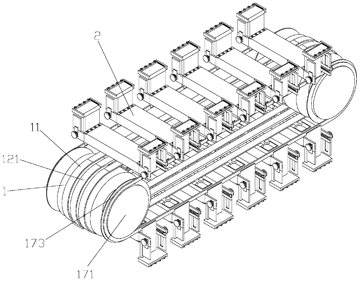
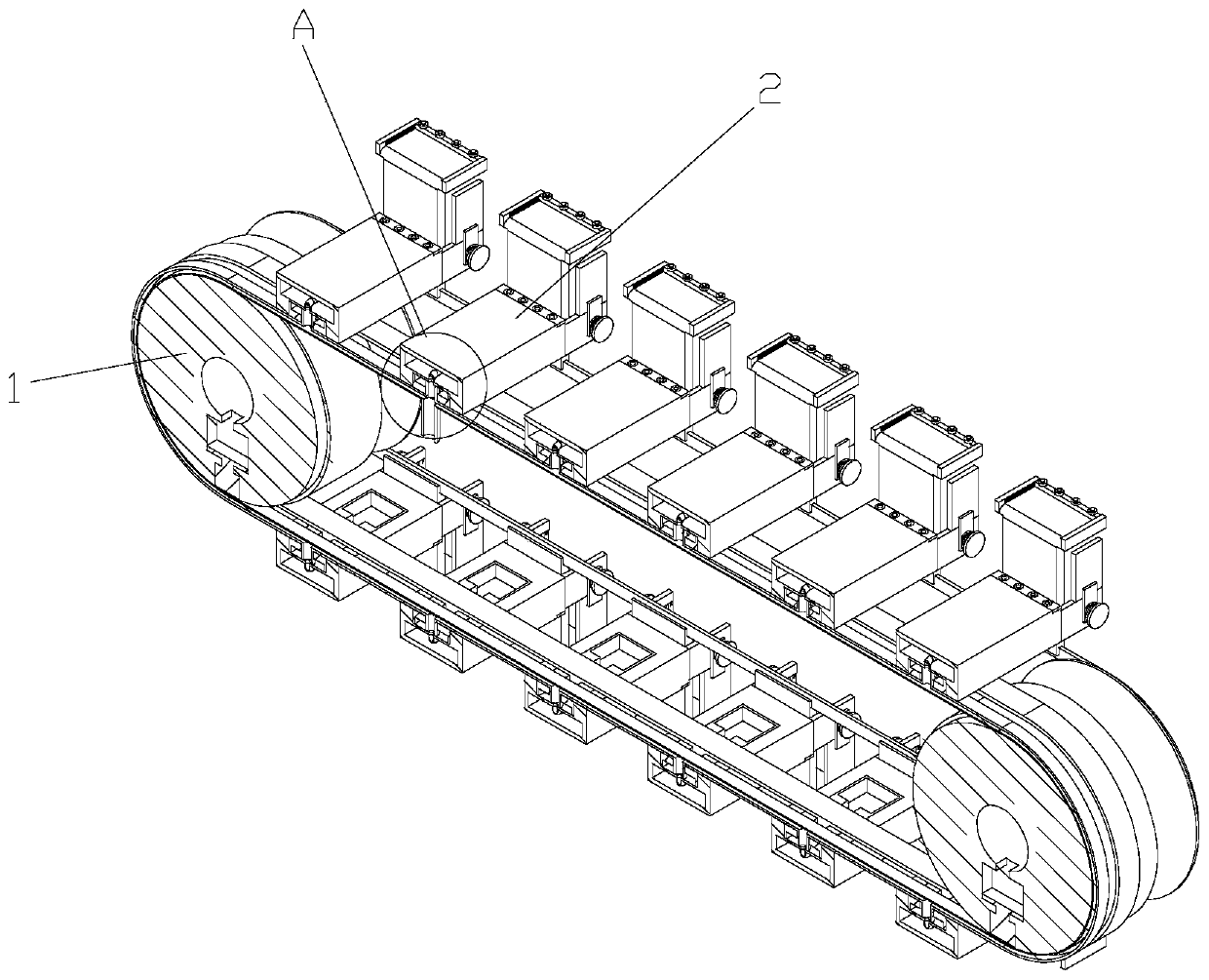
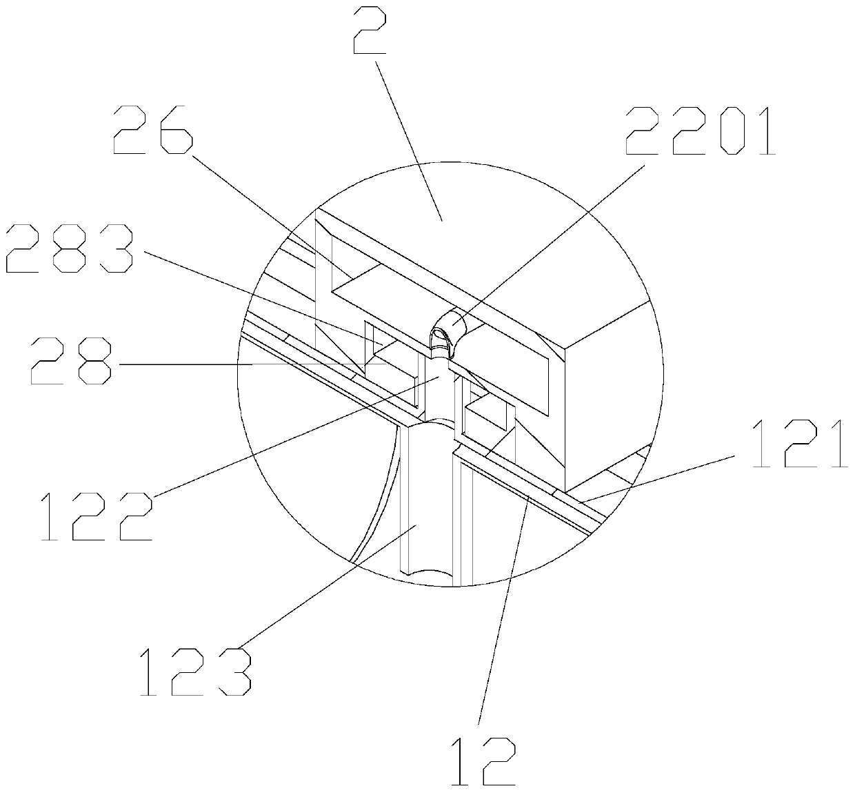
[0037] Such as Figure 1-25As shown, a continuous sponge foaming machine with stable operation includes a rotating roller 1, a first transmission chain 11 arranged on the rotating roller 1 and a support plate 2 arranged on the first transmission chain 11, The support plates 2 are in multiple groups, and are evenly laid on the first transmission chain 11. The first transmission chain is two groups, which are symmetrically arranged on the rollers, so as to improve the stability of the support plates and increase the connection between the support plates and the transmission. Cooperating effect of the chain; the side wall of the support plate 2 is provided with a baffle plate 21, the support plate 2 and the baffle plate 21 are covered with kraft paper, and the side wall of the support plate 2 is provided with a first connecting plate 23 , the first connecting plate 23 is provided with a first chute, and the side wall of the baffle 21 is provided with a first slider matching the f...


PUM


Abstract

The invention discloses an operation stabilized continuous sponge foaming machine. The operation stabilized continuous sponge foaming machine comprises rotary rollers, first transmission chains arranged on the rotary rollers and multiple sets of supporting plates arranged on the first transmission chains. The supporting plates are uniformly laid on the first transmission chains. The sidewalls of the supporting plates are provided with baffles. The supporting plates and the baffle are paved with sulfate paper. The bottom of each supporting plate is provided with a second mounting groove. A third connecting block is mounted in each second mounting groove. Each third connecting block is provided with a limiting groove. The first transmission chains are provided with third limiting plates matched with the limiting grooves. When the supporting plates need maintaining, the limiting grooves and the third limiting plates are combined to push the supporting plates to enable the third limiting plates to move along the inner walls of the limiting grooves, and the third limiting plates are taken out from one sides of the limiting grooves. Through the operation stabilized continuous sponge foaming machine, the supporting plates can be taken down conveniently from the transmission chains to facilitate maintaining, and the maintaining difficulty of the supporting plates is reduced.

Description

technical field [0001] The invention belongs to the technical field of sponge production, in particular to a continuous sponge foaming machine with stable operation. Background technique [0002] Most of the existing foaming machines use fixed molds for foaming. The raw materials are connected to the injection gun head through pipelines, and the gun head is placed in the mold frame loaded with the mold, and then stirred at high speed by the stirring head on the gun head. , and finally pour this raw material into the mold to make it foam into the desired shape; in order to improve the production efficiency of the sponge, the current method is to directly pour the raw material after mixing into the moving corridor so that the sponge is completed during the transmission process Foaming treatment, the corridor used to transport sponges is generally composed of chain plates, and a corridor is formed by multiple chain plates. The chain plates need to be maintained during long-term...

Claims


Application Information

Patent Timeline
Patent Type & Authority Applications(China)
IPC IPC(8): B29C44/34B29C44/60
CPCB29C44/3442B29C44/35B29C44/60
Inventor 方文韬
Owner 方文韬
Why Eureka
Eureka Blog
Learn More